
Optical IQ modulator arbitrary bias point control method and system

A technology of IQ modulator and control method, which is applied in the fields of optical fiber communication and microwave photonics, and can solve problems such as the inability to realize optical IQ modulator, control bias point stability, etc.

Active Publication Date: 2018-11-16
HUAZHONG UNIV OF SCI & TECH
View PDF8 Cites 14 Cited by
  • Summary
  • Abstract
  • Description
  • Claims
  • Application Information

AI Technical Summary

Problems solved by technology

At present, the optimal linear point control of the optical IQ modulator and the arbitrary bias point control of the single MZM modulator have been extensively studied, but these control methods cannot realize the control of the arbitrary bias point of the optical IQ modulator and Maintain the stability of the bias point

Method used


Image

  • Optical IQ modulator arbitrary bias point control method and system
  • Optical IQ modulator arbitrary bias point control method and system
  • Optical IQ modulator arbitrary bias point control method and system

Examples


Embodiment Construction

[0068] In order to make the object, technical solution and advantages of the present invention clearer, the present invention will be further described in detail below in conjunction with the accompanying drawings and embodiments. It should be understood that the specific embodiments described here are only used to explain the present invention, not to limit the present invention. In addition, the technical features involved in the various embodiments of the present invention described below can be combined with each other as long as they do not constitute a conflict with each other.

[0069] Before describing the technical solution of the present invention in detail, the results of the optical IQ modulator are briefly described.

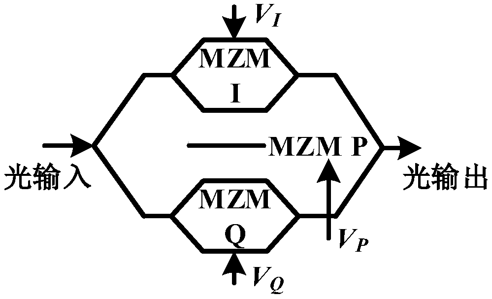
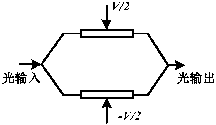
[0070] The structure of a common optical IQ modulator is as follows figure 1 As shown, it contains two sub-Mach-Zehnder modulators (sub-modulator MZMI, sub-modulator MZMQ) and a phase delay P (mother modulator MZMP), in which the two sub-MZM modula...


PUM


Abstract

The invention discloses an optical IQ modulator arbitrary bias point control method and system. The control method comprises: calculating a first type of correlation integral coefficient by using a first disturbance signal and a second disturbance signal; obtaining the characteristic voltage rough values of respective modulators according to a relationship between bias voltages and the first typeof correlation integral coefficients; obtaining the characteristic voltage accurate values of respective modulators by using an iterative method and the characteristic voltage rough values of respective modulators; calculating the bias voltages required to be loaded onto respective modulators at a target bias point, and correspondingly setting the bias voltages required to be loaded onto respective modulators; calculating the value of a second type of correlation integral coefficient by using a third disturbance signal, and accordingly calculating a reference correlation coefficient vector; obtaining a real-time correlation coefficient vector, calculating an error voltage, and then correspondingly adjusting the bias voltages of respective modulators by using the error voltage. The method and system can control any bias point of an optical IQ modulator and maintain the stability of the bias point.

Description

technical field [0001] The invention belongs to the fields of optical fiber communication and microwave photonics, and more specifically relates to a method and a control system for controlling an arbitrary bias point of an optical IQ modulator. Background technique [0002] In optical fiber communication systems, in order to increase channel capacity and increase spectral efficiency, high-order modulation formats such as QPSK, 16QAM, and 64QAM have been widely used. In order to generate an optical signal in a high-order modulation format, an optical in-phase / quadrature-phase (IQ) modulator has been widely used. In addition, because the optical IQ modulator can generate a variety of high-order harmonics when it works at a nonlinear point, the field of microwave photonics also uses the optical IQ modulator to generate multi-frequency radio frequency microwave signals. In order to realize the modulation of signals in high-order modulation formats, the optical IQ modulator nee...

Claims


Application Information

Patent Timeline
Patent Type & Authority Applications(China)
IPC IPC(8): H04B10/516H04L27/20
CPCH04B10/516H04L27/20
Inventor 邓磊李晓雷程孟凡唐明付松年刘德明
Owner HUAZHONG UNIV OF SCI & TECH
Learn More