Denture plate for visual marking and manufacturing method of denture plate

A technology of visual marking and manufacturing methods, which is applied in the fields of dental implants, dentistry, and dental prostheses. It can solve the problems of low preparation efficiency, insufficient installation of dental trays, time-consuming and labor-intensive problems, and achieve the effect of improving reliability.

Active Publication Date: 2018-11-20
BEIJING YAKEBOT TECH CO LTD
View PDF6 Cites 4 Cited by
  • Summary
  • Abstract
  • Description
  • Claims
  • Application Information

AI Technical Summary

Problems solved by technology

The production of dental trays by compression molding requires steps such as preparation of dentition models, compression molding, and polishing, which is time-consuming and labor-intensive, and the production efficiency is low.
The impression method adopts the method of making a silicone rubber impression. The tray is filled with silicone rubber, and the patient bites the tray so that the tray is pasted on the dentition. Although the impression method simplifies the tedious production steps of the compression molding method, it can The dental tray made by the printing film method is not installed firmly enough and the patient is uncomfortable during the occlusal process

Method used


Image

  • Denture plate for visual marking and manufacturing method of denture plate
  • Denture plate for visual marking and manufacturing method of denture plate
  • Denture plate for visual marking and manufacturing method of denture plate

Examples


Embodiment Construction

[0019] In order to make the purpose, technical solutions and advantages of the present invention clearer, the technical solutions in the embodiments of the present invention will be clearly described below in conjunction with the accompanying drawings in the embodiments of the present invention. Obviously, the described embodiments are part of the present invention Examples, not all examples. Based on the embodiments of the present invention, all other embodiments obtained by persons of ordinary skill in the art without making creative efforts belong to the protection scope of the present invention.

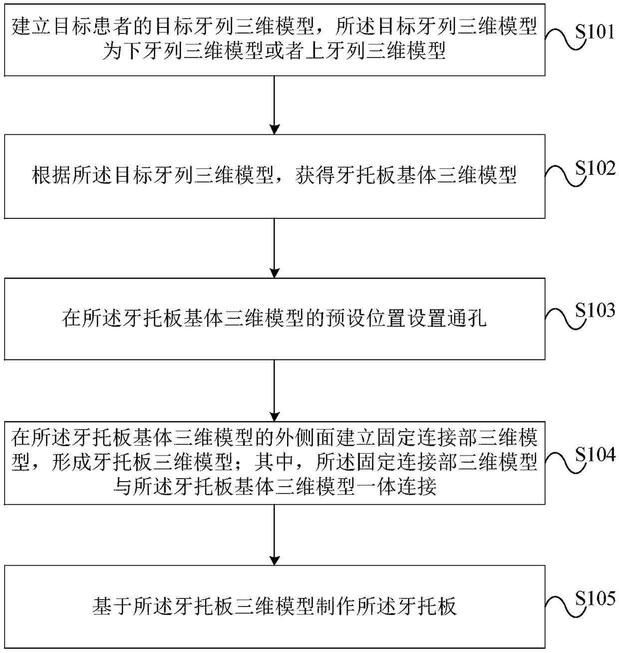
[0020] figure 1 It is a schematic flow chart of a method for making a dental tray for visual marking according to an embodiment of the present invention, such as figure 1 As shown, the dental tray manufacturing method for visual marking provided by the present invention includes:

[0021] S101. Establishing a three-dimensional model of the target dentition of the target patient...


PUM


Abstract

The invention discloses a denture plate for visual marking and a manufacturing method of the denture plate, wherein the manufacturing method comprises the following steps: establishing a three-dimensional model for a target dentition of a target patient; acquiring a denture plate matrix three-dimensional model according to the three-dimensional model for the target dentition; arranging a through hole in a default location of the denture plate matrix three-dimensional model; establishing a fixed connecting part three-dimensional model on the outer side surface of the denture plate matrix three-dimensional model, and forming a denture plate three-dimensional model, wherein the fixed connecting part three-dimensional model and the denture plate matrix three-dimensional model are integrally connected; and the denture plate is made on the basis of the denture plate matrix three-dimensional model. The denture plate is manufactured by adopting the method. The provided denture plate for visualmarking and the manufacturing method of the denture plate can fit with the lower dentition or the upper dentition of the patient, so that the denture plate is fixed on the lower denture plate or theupper denture plate, a visual marking plate is fixedly connected through a fixed connecting part, and the installation and fixation reliability of the denture plate is improved.

Description

technical field [0001] The invention relates to the technical field of intelligent manufacturing, in particular to a dental tray for visual marking and a manufacturing method thereof. Background technique [0002] The intelligent and high-precision characteristics of the robot make it have unique advantages in the application of stomatology. Due to the fine and complex structure in the oral cavity, it is necessary to use the positioning and navigation system of the robot to perform precise positioning to improve the treatment effect. [0003] For robotic dental implant surgery, whether the implant can be placed in an accurate position in the jawbone is one of the main factors affecting the implant effect. Robot-assisted dental implant surgery requires a dental tray to firmly connect the visual markers with the patient's jaw. The positioning and navigation system of the robot indirectly locates the preset implant position by recognizing the visual markers. The dental tray cu...

Claims


Application Information

Patent Timeline
Patent Type & Authority Applications(China)
IPC IPC(8): A61C9/00A61C8/00
CPCA61C8/009A61C9/004A61C1/084A61C13/0004A61C5/90A61C17/06G06T2207/30036A61C9/0046A61C13/34G06T17/00
Inventor 王利峰沈晨任建勇刘洪澎
Owner BEIJING YAKEBOT TECH CO LTD
Why Eureka
Try Eureka