Orthopaedic rehabilitation nursing device

A nursing device and orthopedic rehabilitation technology, applied in physical therapy, roller massage, passive exercise equipment, etc., can solve problems such as ineffective exercise of limbs and joints, no muscle massage and exercise, and inability to move limbs and joints, etc., to achieve Reduce the probability of occurrence, change the direction of leg traction, and reduce the effect of muscular dystrophy

Active Publication Date: 2018-11-20
HENAN PROVINCE HOSPITAL OF TCM THE SECOND AFFILIATED HOSPITAL OF HENAN UNIV OF TCM
View PDF10 Cites 19 Cited by
  • Summary
  • Abstract
  • Description
  • Claims
  • Application Information

AI Technical Summary

Problems solved by technology

[0005] In view of the above problems, the present invention provides an orthopedic rehabilitation nursing device, which effectively solves the problem that patients with orthopedic injuries cannot move limb joints after sitting for a long time, and also solves the problem that limb joints cannot be effectively exercised in the prior art, and traction Single effect, inconvenient to use, no problem with muscle massage and exercise functions

Method used


Image

  • Orthopaedic rehabilitation nursing device
  • Orthopaedic rehabilitation nursing device
  • Orthopaedic rehabilitation nursing device

Examples


Embodiment 1

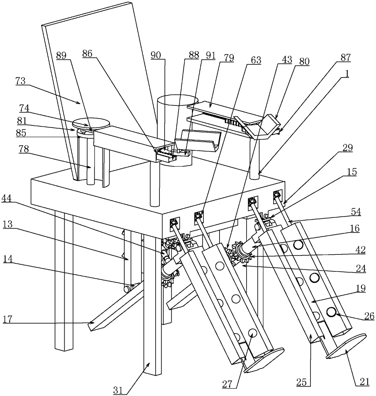
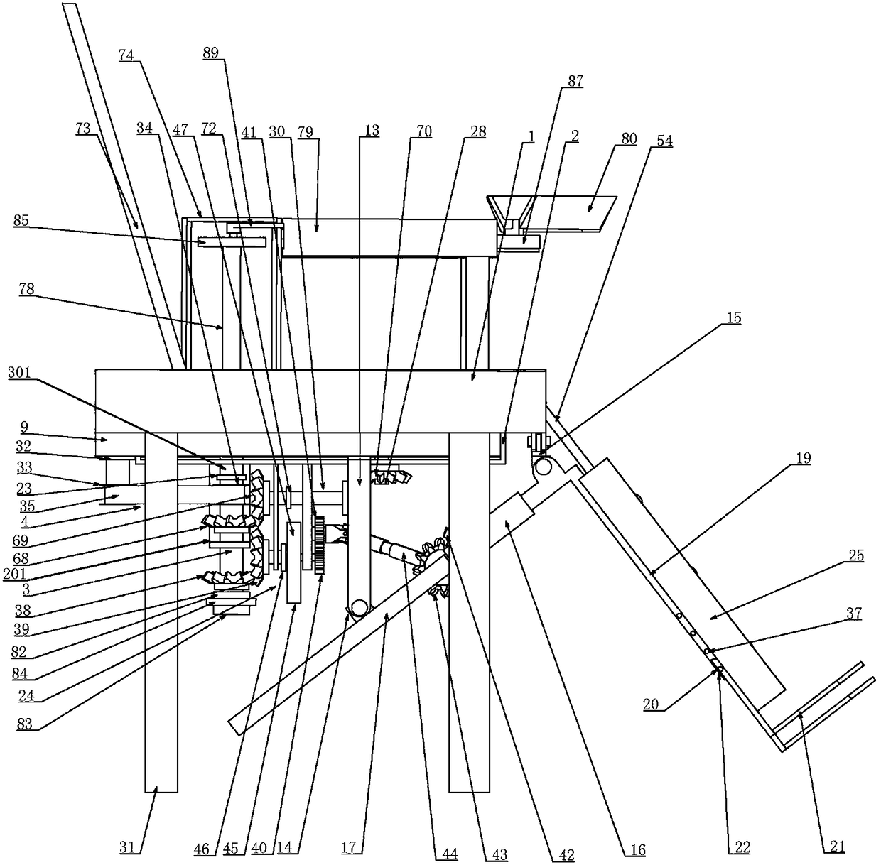
[0039] Embodiment one, combined with the attached Figure 1-11 , an orthopedic rehabilitation nursing device, comprising a housing 1, the housing 1 is an internal hollow structure, characterized in that the lower end of the housing 1 is covered with a U-shaped plate 2 along the left and right directions, and the U-shaped plate 2 is 1 is set in the length direction, the opening direction of the U-shaped plate 2 is set upwards, the lower end of the U-shaped plate 2 is fixedly connected to an L-shaped fixed plate 201, and the bottom of the U-shaped plate 2 is provided with a vertical rotation connection The main shaft 3 on the fixed plate 201, the upper shaft end of the main shaft 3 is not in contact with the bottom end of the U-shaped plate 2, and the lower end extends downward, and the main shaft 3 is driven by the driving device 4 fixedly connected to the lower end of the housing 1 , the driving device 4 provides power input for the main shaft 3, and a vertical driving shaft 3...

Embodiment 2

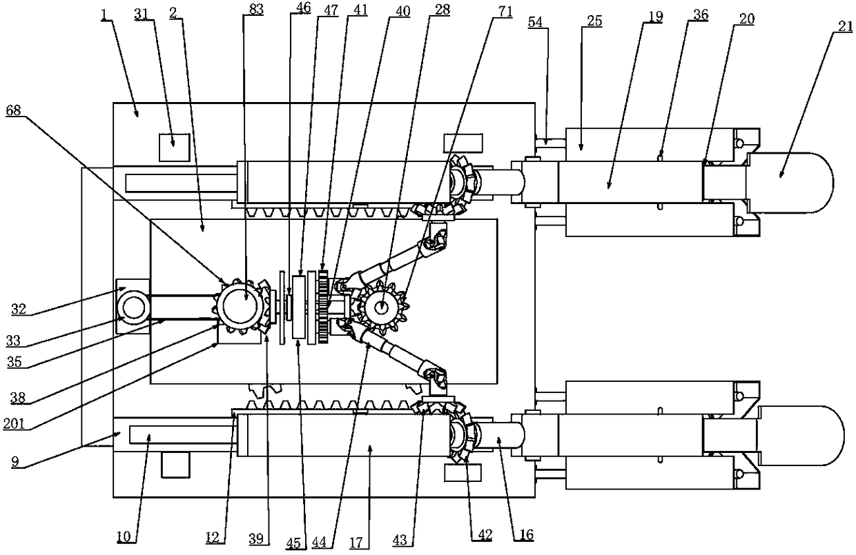
[0047] Embodiment two, on the basis of embodiment one, in conjunction with the attached Figure 1-11 , the drive device 4 includes a drive motor 32 connected to the lower end of the housing 1, the output shaft of the drive motor 32 is coaxially connected to a first pulley 33, and also includes a second pulley 34 coaxially connected to the main shaft 3, A first belt 35 is sheathed between the first pulley 33 and the second pulley 34, and the main shaft 3 transmits power from the drive motor 32 to itself through the first belt 35 to provide power input for itself.

Embodiment 3

[0048] Embodiment three, on the basis of embodiment two, in conjunction with appended Figure 1-11 The adjusting and clamping structure 22 includes elastic pins 36 connected to the front and rear side walls of the pedal 21, and also includes pin holes 37 arranged on the front and rear inner walls of the chute 20 at intervals along the length direction of the chute 20, correspondingly The elastic pin 36 on the corresponding side wall is axially slidably matched with the pin hole 37. When adjustment is required, the head of the elastic pin 36 is pressed into the pin hole 37, and then the pedal 21 and the support plate 19 can be adjusted. Relatively slide, adjust the position of the pedal 21 until it is suitable for the patient's leg length, then cancel the pressing of the elastic pin 36, and the pin hole 37 pops up from the column head, thereby limiting the relative displacement between the pedal 21 and the support plate 19, and playing a role The clamping function is added to a...


PUM


Abstract

The invention relates to an orthopaedic rehabilitation nursing device. A first fan-shaped gear and a second fan-shaped gear are driven by a main shaft to alternately mesh with a first rack, so that avertical rod drives a square rod and a supporting plate to swing in the left and right directions; by arranging a left and right swing driving device, a reversing device is driven through the main shaft, so that a telescoping universal coupling drives a third bevel gear to rotate, a rotary rod is made to drive the supporting plate to swing in the front and back directions, and the knee joints aresufficiently exercised; the main shaft drives a massage device through a massage driving device, massage balls can fully massage leg muscles, and since the legs swing in various directions, the knee joints are sufficiently exercised; traction directions are changeable, the orthopaedic rehabilitation nursing device is convenient to use, the elbow joints of the arms are well massaged, and the muscleatrophy disease incidence rate is reduced; the main shaft further drives arm swing devices, the elbow joints of the arms are sufficiently exercised, and the rehabilitation nursing effect is remarkable; by adding a clutch, a user conveniently controls the orthopaedic rehabilitation nursing device, the device can be used according to the needs, and also can be cooperatively used, and the device isconvenient to use and practical.

Description

technical field [0001] The invention belongs to the technical field of orthopedic surgery, in particular to an orthopedic rehabilitation nursing device. Background technique [0002] "One hundred days of bone injury" is a well-known folk proverb for postoperative recovery of orthopedic patients. For orthopedic surgery patients, fractures are often a relatively common orthopedic surgery injury. Post-care plays a particularly important role in the entire recovery stage of orthopedic patients. For orthopedic patients, fractures of limbs are more difficult to deal with, because patients with fractures cannot perform strenuous activities, otherwise the wounds that have been connected will be damaged. If a patient suffers a secondary injury, assuming a patient has a fractured calf, the leg cannot move with force, which will cause muscle atrophy after a long time, and at the same time, the joints of the lower limbs will not be exercised effectively, which will adversely affect the ...

Claims


Application Information

Patent Timeline
Patent Type & Authority Applications(China)
IPC IPC(8): A61H1/02A61H15/00
CPCA61H1/024A61H1/0277A61H15/0078A61H2015/005A61H2201/1207A61H2205/06A61H2205/10A61H2205/102
Inventor 鲁花
Owner HENAN PROVINCE HOSPITAL OF TCM THE SECOND AFFILIATED HOSPITAL OF HENAN UNIV OF TCM
Why Eureka
Try Eureka