Anti-shaft-wrapping structure and anti-shaft-wrapping method of concrete mixer

A concrete mixer and mixing shaft technology, which is applied to mixer accessories, mixers, cement mixing devices, etc., can solve problems such as shaft wrapping and lack of special research, reducing the number of cleanings, saving maintenance costs for mechanical parts, and mixing efficiency. boosted effect

Pending Publication Date: 2018-11-20
ZHENGZHOU MUNICIPAL ENG CORP
View PDF0 Cites 0 Cited by
  • Summary
  • Abstract
  • Description
  • Claims
  • Application Information

AI Technical Summary

Problems solved by technology

[0005] In the past, the reasons for the phenomenon of shaft w

Method used


Image

  • Anti-shaft-wrapping structure and anti-shaft-wrapping method of concrete mixer
  • Anti-shaft-wrapping structure and anti-shaft-wrapping method of concrete mixer
  • Anti-shaft-wrapping structure and anti-shaft-wrapping method of concrete mixer

Examples


Embodiment Construction

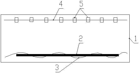
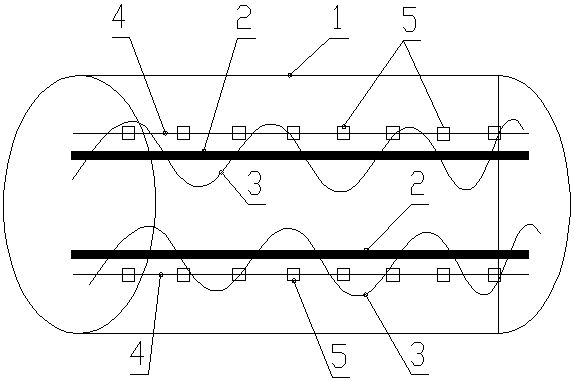
[0040] Such as Figure 1 to Figure 6 As shown, the anti-wrapping shaft structure of the concrete mixer of the present invention includes a mixing tank 1 of the mixer, and two mixing shafts 2 are arranged side by side on the same horizontal plane in the mixing tank 1, and each mixing shaft 2 is provided with a spiral mixing blade 3;

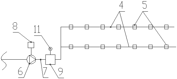
[0041] A flushing water pipe 4 is arranged on the top of each stirring shaft 2, and a plurality of nozzles 5 are installed at intervals on each flushing water pipe 4. The water spraying area forms a cone-shaped area from top to bottom, and the angle α between the two busbars on the same vertical section of the cone-shaped area is 65±2 degrees; this angle can ensure that the agitator shaft that cannot be washed in the past can be washed 2 dead angle, flush the stirring shaft 2 without dead angle.

[0042] A flushing water pump 6 is arranged outside the mixing tank 1, and the water inlet of the flushing water pump 6 is connected to an external wate...


PUM


Abstract

The invention discloses an anti-shaft-wrapping structure of a concrete mixer. The anti-shaft-wrapping structure of the concrete mixer comprises a stirring tank of a stirring machine, wherein a flushing pipe is arranged above each stirring shaft of the stirring tank; multiple spray heads are arranged on each flushing pipe in a spaced manner; the center of a water spraying direction of each spray head directly faces the corresponding stirring shaft below; a water spraying area of each spray head forms a conical area from top to bottom; an included angle alpha of two busbars, located on the samevertical cross section, of each conical area is 65+/-2 degrees; a flushing water pump is arranged outside the stirring tank; a water outlet of the flushing water pump is connected with each flushing pipe through a water outlet pipe; the flushing water pump is connected with an electronic control device; a pressure water tank is arranged on the water outlet pipe; a pressure sensor is arranged on the pressure water tank; an the working pressure of the pressure water tank is 0.33+/-0.03MPa. The invention further discloses an anti-shaft-wrapping method using the anti-shaft-wrapping structure. According to the anti-shaft-wrapping structure and the anti-shaft-wrapping method of the concrete mixer provided by the invention, the occurrence of the shaft-wrapping phenomenon is greatly reduced by 75percent compared with the prior art, the stirring efficiency is remarkably improved, and the electricity consumption, the labor cost, the maintenance fitter cost and the mechanical accessory maintenance cost are saved.

Description

technical field [0001] The invention relates to the technical field of concrete construction, in particular to an anti-wrapping shaft structure and an anti-wrapping method of a concrete mixer. Background technique [0002] In recent years, ready-mixed concrete has been widely used in urban and rural areas. At present, there are 150 ready-mixed concrete companies in the main urban area of ​​Zhengzhou City, and the market is seriously oversupplied. The profits of each ready-mixed concrete company are low, and the industry competition is fierce. Improving competitiveness by reducing costs and increasing efficiency has become an important way for enterprises to survive and develop. [0003] At present, in the production process, the production efficiency of the mixer is low, and it can only reach 75% of the designed production capacity. The use cost is high and affects the supply of concrete. Low production efficiency leads to prolonged mixing time, high equipment wear and pow...

Claims


Application Information

Patent Timeline
IPC IPC(8): B28C5/08B01F15/00
CPCB28C5/0806B01F35/1453
Inventor 王明远光军伟吴纪东尚国宣张双梅陈波李琪勇刘军李乐辉赵娜张亮任清秦善勇申振国武鹏年王玉芳李永治李巍赵忠心罗华丽罗华琦许瑞峰王凌欣焦改霞焦峰
Owner ZHENGZHOU MUNICIPAL ENG CORP
Why Eureka
Try Eureka