System and method for detecting static parameters of high-speed rail track based on fiber-optic inertial navigation

A fiber optic inertial navigation and static parameter technology, which is applied in the direction of track, track maintenance, track superstructure, etc., can solve the problems of inability to take into account both internal and external parameter measurement, high use requirements, and incomplete measurement parameters.

Active Publication Date: 2018-11-20
HUBEI SANJIANG AEROSPACE HONGFENG CONTROL
View PDF10 Cites 14 Cited by
  • Summary
  • Abstract
  • Description
  • Claims
  • Application Information

AI Technical Summary

Problems solved by technology

Patent CN103754235A discloses an inertial positioning and orientation device and method for high-speed rail measurement. Although the measurement efficiency and accuracy are improved, and the measurement parameters are relatively comprehensive, the parts related to the optical fiber inertial navigation are too complicated, and the accuracy and use requirements of the inertial navigation Both are very high, and it is not convenient to introduce the parameters on the measurement and control network
[0006] To sum up, the existing measurement methods have incomplete measurement parameters, cannot take into account the measurement of internal and external parameters at the same time, the structure of the fiber-optic inertial navigation is complex, and the requirements for the accuracy and use of the fiber-optic inertial navigation are high.

Method used


Image

  • System and method for detecting static parameters of high-speed rail track based on fiber-optic inertial navigation
  • System and method for detecting static parameters of high-speed rail track based on fiber-optic inertial navigation
  • System and method for detecting static parameters of high-speed rail track based on fiber-optic inertial navigation

Examples


Embodiment Construction

[0062] In order to make the object, technical solution and advantages of the present invention clearer, the present invention will be further described in detail below in conjunction with the accompanying drawings and embodiments. It should be understood that the specific embodiments described here are only used to explain the present invention, not to limit the present invention. In addition, the technical features involved in the various embodiments of the present invention described below can be combined with each other as long as they do not constitute a conflict with each other.

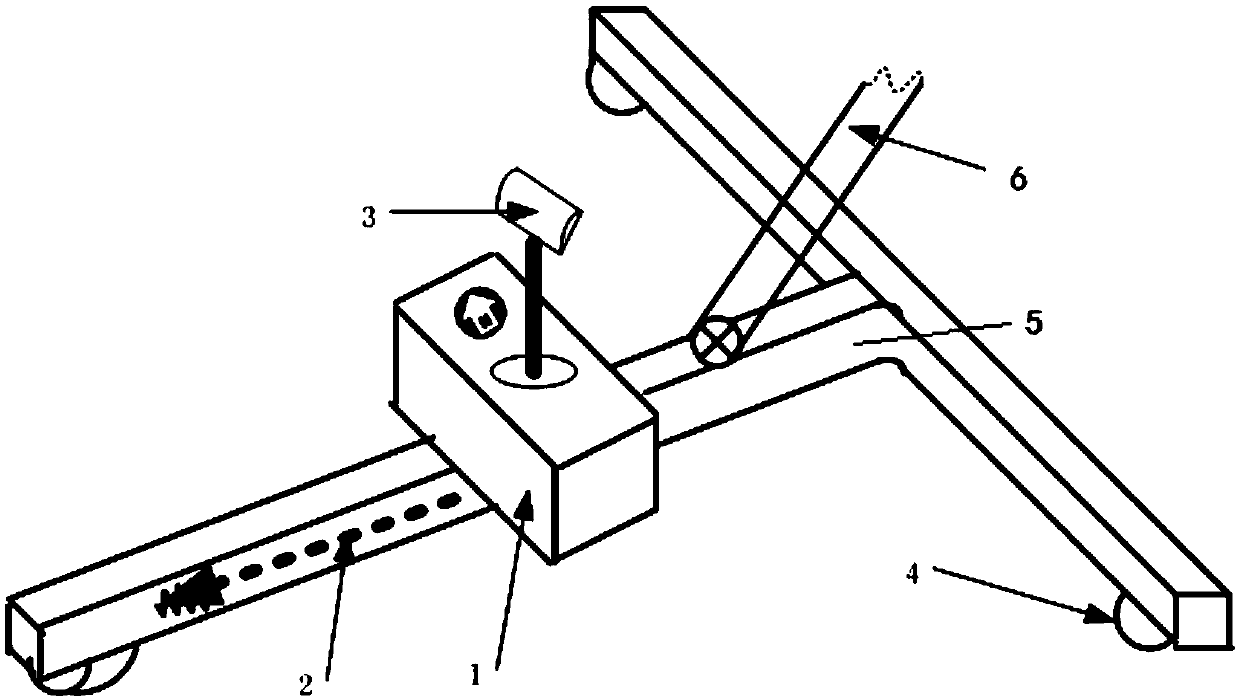
[0063] The high-speed rail static parameter detection device using optical fiber inertial navigation includes a prism inertial navigation track inspection trolley, a high-precision total station, a data acquisition and processing device, a signal transmission device, a battery and a night lighting mechanism.

[0064] figure 1 It is a schematic diagram of the hardware composition of the inertial...


PUM


Abstract

The invention discloses a system for detecting static parameters of a high-speed rail track based on fiber-optic inertial navigation. The system comprises a signal transmission device, a data acquisition and processing device and a T-shaped trolley frame (5), wherein a gauge measuring device (2) is arranged in the T-shaped trolley frame (5), a fiber-optic inertial navigation system (1) is arrangedon the upper surface of the T-shaped trolley frame (5), a vehicle prism (3) is arranged on the top of the fiber-optic inertial navigation system (1), wheels and odometers are arranged at three end points of the T-shaped trolley frame (5), connectors (4) for the wheels and the odometers are arranged between the corresponding wheels and odometers, and the fiber-optic inertial navigation system (1)receives signals from the three-way odometers, the gauge measuring device (2) and the connectors (4) for the wheels and the odometers, and interacts with information of a data acquisition and processing device to obtain data. The invention further discloses a method for detecting the static parameters of the high-speed rail track based on the fiber-optic inertial navigation. The system for detecting static parameters of the high-speed rail track based on the fiber-optic inertial navigation can realize continuous measurement of internal and external parameters.

Description

technical field [0001] The invention belongs to the technical field of static detection of high-speed rail track measurement, and more particularly relates to a system and method for detecting static parameters of high-speed rail tracks using optical fiber inertial navigation. Background technique [0002] In the stages of survey, construction, operation and maintenance of high-speed railways, in order to ensure the quality of high-speed railways, the basic frame plane control network CP0, the basic plane control network CPⅠ, the line plane control network CPⅡ, and the track control network CPⅢ have been established in the project. CPⅢ starts and closes CPⅠ or CPⅡ, and the CPⅢ control point is an independent control network with high internal matching accuracy, and the relative point error between adjacent points is less than 1mm. In order to ensure the consistency of the plane measurement results, the project requires "three networks in one". [0003] During static measure...

Claims


Application Information

Patent Timeline
IPC IPC(8): E01B35/00
CPCE01B35/00E01B2203/16
Inventor 王勇刚彭志强李亮李亚珍翁海诠
Owner HUBEI SANJIANG AEROSPACE HONGFENG CONTROL
Why Eureka
Try Eureka