Cement floor paving equipment used for building construction

A construction and cement technology, applied in the field of cement floor laying equipment for construction, can solve the problems of high labor intensity, uneven cement laying, slow laying speed, etc.

Inactive Publication Date: 2018-11-20
黄玉发
View PDF5 Cites 10 Cited by
  • Summary
  • Abstract
  • Description
  • Claims
  • Application Information

AI Technical Summary

Problems solved by technology

[0003] During building construction, it is often necessary to lay cement floors. To lay cement floors, you first need to pour the prepared cement slurry on the ground where the equipment needs to be laid, and then the staff squats in front of the poured cement slurry and uses tools. Smooth the cement slurry, so that the way of manually paving the cement can easily lead to uneven cement paving, and the paving speed is slow and labor-intensive

Method used


Image

  • Cement floor paving equipment used for building construction
  • Cement floor paving equipment used for building construction
  • Cement floor paving equipment used for building construction

Examples


Embodiment 1

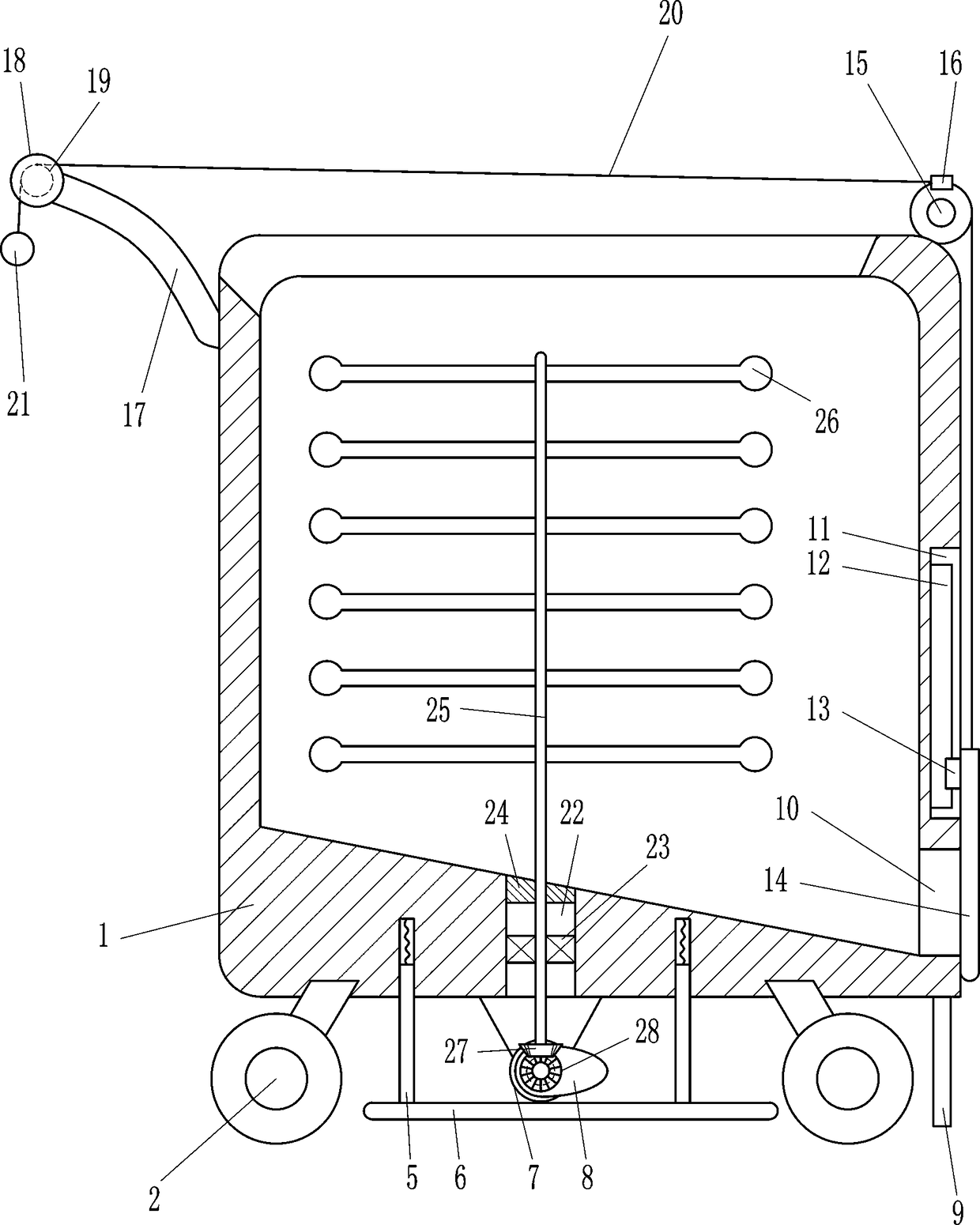
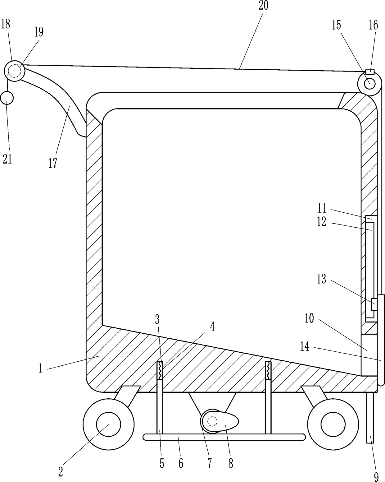
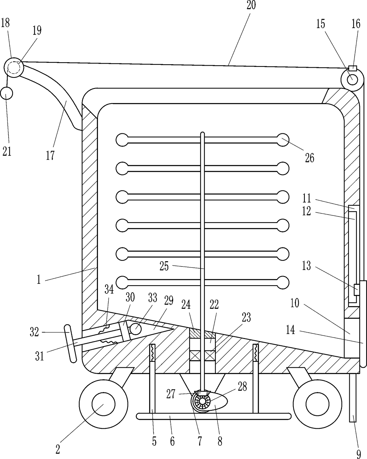
[0019] A kind of cement floor laying equipment for building construction, such as Figure 1-3 As shown, it includes frame body 1, wheel 2, first spring 4, guide rod 5, pressing plate 6, motor 7, cam 8, push plate 9, slide rail 12, slider 13, baffle plate 14, fixed pulley 15, Blocks 16, connecting rods 17, push rods 18, pull wires 20 and pull balls 21, wheels 2 are installed at the bottom of the frame body 1, guide grooves 3 are opened on the left and right sides of the bottom of the frame body 1, and the guide grooves 3 on the left and right sides The upper inner wall is connected with the first spring 4, and the bottom ends of the first springs 4 on the left and right sides are connected with guide rods 5, and the upper parts of the guide rods 5 on the left and right sides are all slidably positioned in the guide groove 3, and the guide rods on the left and right sides The bottom end of the rod 5 is connected with a pressure plate 6, the middle part of the lower side of the f...

Embodiment 2

[0021] A kind of cement floor laying equipment for building construction, such as Figure 1-3 As shown, it includes frame body 1, wheel 2, first spring 4, guide rod 5, pressing plate 6, motor 7, cam 8, push plate 9, slide rail 12, slider 13, baffle plate 14, fixed pulley 15, Blocks 16, connecting rods 17, push rods 18, pull wires 20 and pull balls 21, wheels 2 are installed at the bottom of the frame body 1, guide grooves 3 are opened on the left and right sides of the bottom of the frame body 1, and the guide grooves 3 on the left and right sides The upper inner wall is connected with the first spring 4, and the bottom ends of the first springs 4 on the left and right sides are connected with guide rods 5, and the upper parts of the guide rods 5 on the left and right sides are all slidably positioned in the guide groove 3, and the guide rods on the left and right sides The bottom end of the rod 5 is connected with a pressure plate 6, the middle part of the lower side of the f...

Embodiment 3

[0024] A kind of cement floor laying equipment for building construction, such as Figure 1-3As shown, it includes frame body 1, wheel 2, first spring 4, guide rod 5, pressing plate 6, motor 7, cam 8, push plate 9, slide rail 12, slider 13, baffle plate 14, fixed pulley 15, Blocks 16, connecting rods 17, push rods 18, pull wires 20 and pull balls 21, wheels 2 are installed at the bottom of the frame body 1, guide grooves 3 are opened on the left and right sides of the bottom of the frame body 1, and the guide grooves 3 on the left and right sides The upper inner wall is connected with the first spring 4, and the bottom ends of the first springs 4 on the left and right sides are connected with guide rods 5, and the upper parts of the guide rods 5 on the left and right sides are all slidably positioned in the guide groove 3, and the guide rods on the left and right sides The bottom end of the rod 5 is connected with a pressure plate 6, the middle part of the lower side of the fr...


PUM


Abstract

The invention relates to floor paving equipment, in particular to cement floor paving equipment used for building construction, and aims to provide the cement floor paving equipment used for buildingconstruction which can rapid pave cement floor and is low in labor intensity. Through the technical scheme, the cement floor paving equipment used for building construction comprises a frame body, wheels, first springs, a guide rod, a pressure plate, a motor, a cam, a push plate, a sliding rail, a sliding block, a baffle plate, a fixed pulley, a clamping block, a connecting rod and the like; the wheels are mounted at the bottom of the frame body, guide grooves are formed in the left and right sides of the bottom of the frame body, and the upper inner walls of the guide grooves in the left andright sides are connected with the first springs respectively. Through the arrangement of the push plate, a cement paste can be pushed easily when the equipment is pushed by people, and the pressure plate can be used for rapidly paving cement on the ground due to the cooperation of the cam and the pressure plate, so that the working strength of workers is reduced.

Description

technical field [0001] The invention relates to a ground laying equipment, in particular to a cement ground laying equipment for building construction. Background technique [0002] Cement floor is the ground paved with concrete mixed with cement. Whether in the city or in the countryside, concrete floors can be seen everywhere. People will set the width of the concrete floor according to the size of the flow of people. At the same time, the thickness of the concrete floor is also determined according to different actual flow of people and vehicles. [0003] During building construction, it is often necessary to lay cement floors. To lay cement floors, you first need to pour the prepared cement slurry on the ground where the equipment needs to be laid, and then the staff squats in front of the poured cement slurry and uses tools. The cement slurry is smoothed, and the way of manually paving the cement in this way is easy to cause the cement to be uneven, and the speed of la...

Claims


Application Information

Patent Timeline
IPC IPC(8): E01C19/18
CPCE01C19/187
Inventor 黄玉发
Owner 黄玉发
Why Eureka
Try Eureka