Counterweight device for detecting ballast test through engineering pile foundation

A technology of counterweight device and engineering pile, which is applied in the test of foundation structure, foundation structure engineering, construction, etc. It can solve the problems of scratches on the load-bearing box, counterweight boxes that cannot be tightly embedded with each other, and a single type of storage slot. , to achieve the effect of improving service life and aesthetics, good safety and assembly, safe and easy to assemble and disassemble

Inactive Publication Date: 2018-11-20
周惠荣
View PDF0 Cites 4 Cited by
  • Summary
  • Abstract
  • Description
  • Claims
  • Application Information

AI Technical Summary

Problems solved by technology

Therefore, each foundation design and treatment specification puts the single pile static load test at the top of the list, and the method used in the static load test is mostly stacking multiple concrete blocks on the ballast load-bearing platform, which will consume a lot of manpower and material resources , and the overall collapse often occurs, which will cause personal injury to the staff
[0003] The existing counterweight device has certain disadvantages in use. First, when the device is in use, it directly contacts the ground to generate vibration, which is easy to damage the internal components, and the outer surface of the load-bearing box will also have scratches, which affects the aesthetics of use. , when the counterweight box is stacked, the sides cannot be tightly embedded with each other, and it does not have the function of assembly. It is troublesome and unsafe to handle. For this reason, we propose a counterweight device for engineering pile foundation detection ballast test

Method used


Image

  • Counterweight device for detecting ballast test through engineering pile foundation
  • Counterweight device for detecting ballast test through engineering pile foundation
  • Counterweight device for detecting ballast test through engineering pile foundation

Examples


Embodiment Construction

[0018] In order to make the technical means, creative features, goals and effects achieved by the present invention easy to understand, the present invention will be further described below in conjunction with specific embodiments.

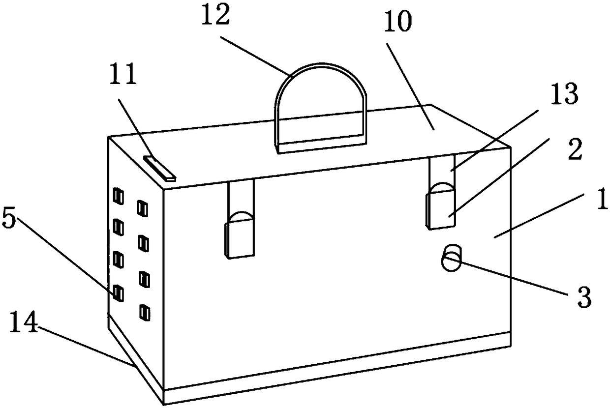
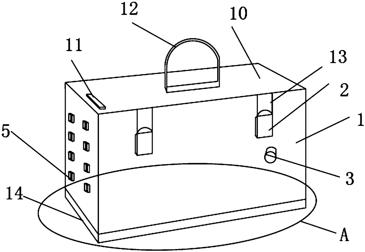
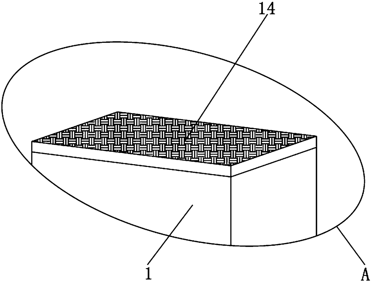
[0019] Such as Figure 1-4 As shown, a counterweight device for engineering pile foundation detection and ballast testing includes a load-bearing box 1 and a control key 11, and a hasp lock 2 is fixedly installed on the outer surface of the load-bearing box 1, and the hasp lock 2 An alarm 3 is provided below, a groove connection port 4 is fixedly installed on one side of the bearing box 1, and a connecting bump 5 is fixedly installed on the other side of the bearing box 1, the bearing box 1 The inner surface is provided with a buffer layer 6, and the inner surface of the buffer layer 6 is provided with a square storage slot 7, and one side of the square storage slot 7 is provided with a circular storage slot 8, and one side of the circular storage...


PUM


Abstract

The invention discloses a counterweight device for detecting ballast test through an engineering pile foundation. The counterweight device comprises a bearing box and a control key, a buckle lock is fixedly mounted on the outer surface of the bearing box, a groove connecting opening is fixedly mounted in one side of the bearing box, a buffer layer is arranged on the inner surface of the bearing box, and a round storing groove is formed in one side of a square storing groove; and a box cover is arranged on the upper portion of the bearing box. According to the counterweight device for detectingballast test through the engineering pile foundation, a damping cushion layer, the groove connecting opening and an alarm are arranged, the damping buffering and protecting can be conducted on a mainbody of the equipment, the normal work of the internal components is ensured, the service life of the equipment is indirectly prolonged, all the side faces of the counterweight boxes can be conveniently and tightly inlaid with one another during stacking, the counterweight device is safe and easy to assemble, alerts can be issued when the inlaid docking is not thorough, the counterweight device is suitable for different working conditions, and the better prospects are brought to use.

Description

technical field [0001] The invention relates to the field of counterweight device equipment, in particular to a counterweight device for engineering pile foundation detection and ballast testing. Background technique [0002] At present, the method of engineering pile foundation detection is called static load detection test, and pile foundation static load test is a technology used in engineering to detect the bearing capacity of pile foundations. In terms of determining the ultimate bearing capacity of a single pile, it is the most accurate and reliable inspection method at present. As a judgment of whether a certain dynamic load inspection method is mature, it is based on the comparative error of the static load test results. Therefore, each foundation design and treatment specification puts the single pile static load test in the first place, and the method used in the static load testing test is mostly stacking multiple concrete blocks on the ballast load-bearing platfo...

Claims


Application Information

Patent Timeline
Patent Type & Authority Applications(China)
IPC IPC(8): E02D33/00
CPCE02D33/00E02D2300/0001
Inventor 周惠荣
Owner 周惠荣
Why Eureka
Try Eureka