Rear H-shaped steel cantilever scaffold and construction method thereof

A technology of cantilevered scaffolding and construction method, applied in the field of scaffolding, can solve the problems of damage to existing concrete floors, low strength of floor concrete, affecting the construction of cantilevered scaffolding, etc., to achieve the safety of cantilevered scaffolding, a wide range of use, and reduced restrictions desired effect

Inactive Publication Date: 2018-11-20
GUANGDONG PROVINCIAL ACAD OF BUILDING RES GRP CO LTD +1
View PDF7 Cites 0 Cited by
  • Summary
  • Abstract
  • Description
  • Claims
  • Application Information

AI Technical Summary

Problems solved by technology

[0003] ⑴ Drill holes to embed components on the existing floor, and the force of the existing concrete floor on the first floor will cause damage to the existing concrete floor
[0006] ② Some existing buildings have been built for a long time, and the concrete strength of the floor slab is not high, which affects the construction of cantilevered scaffolding

Method used


Image

  • Rear H-shaped steel cantilever scaffold and construction method thereof
  • Rear H-shaped steel cantilever scaffold and construction method thereof
  • Rear H-shaped steel cantilever scaffold and construction method thereof

Examples


Embodiment Construction

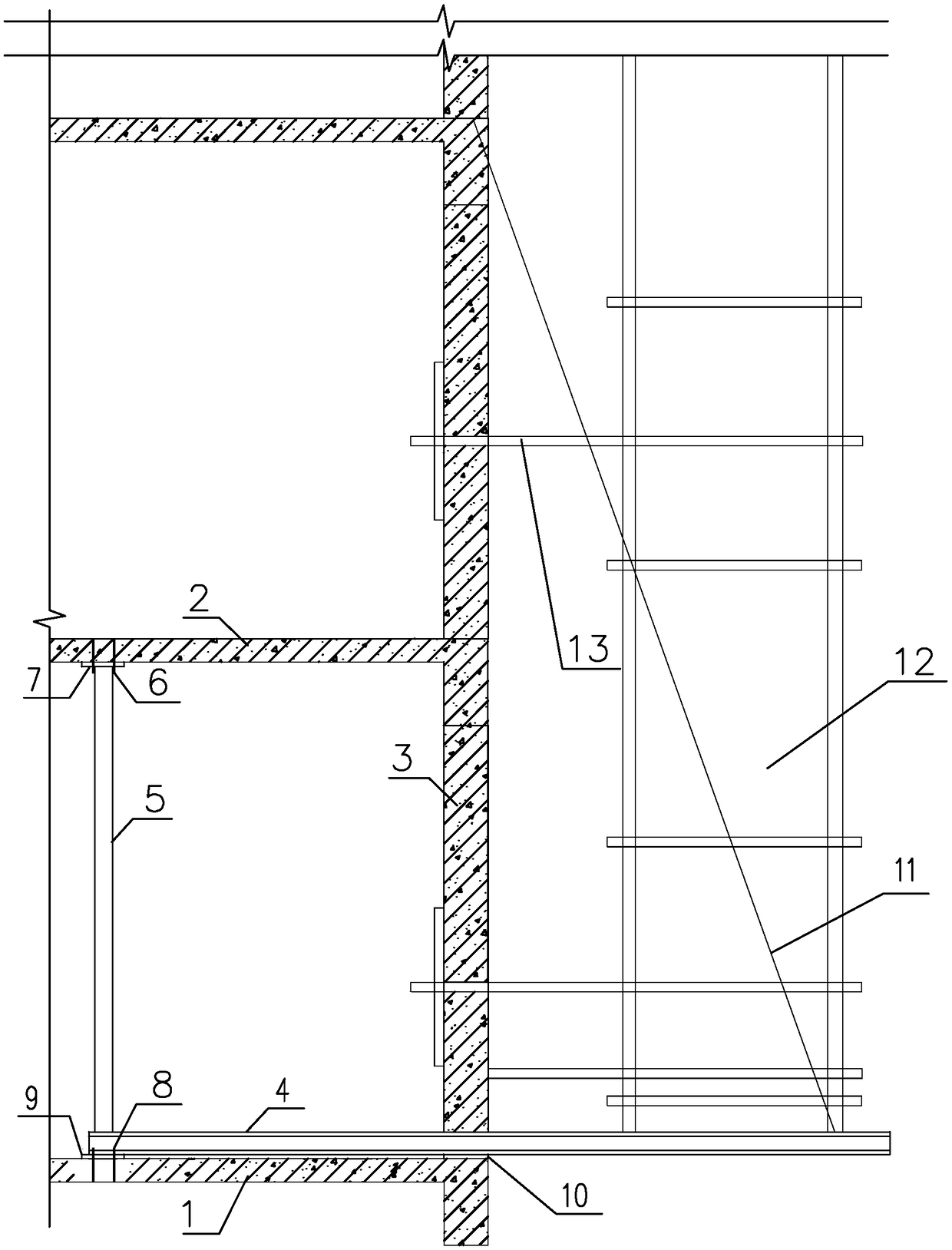
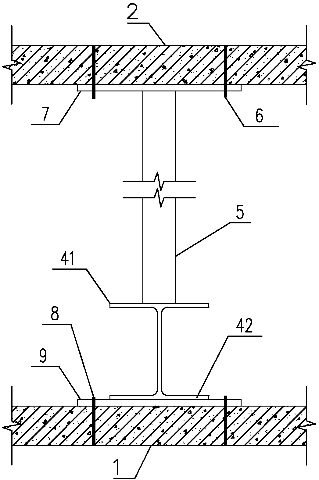
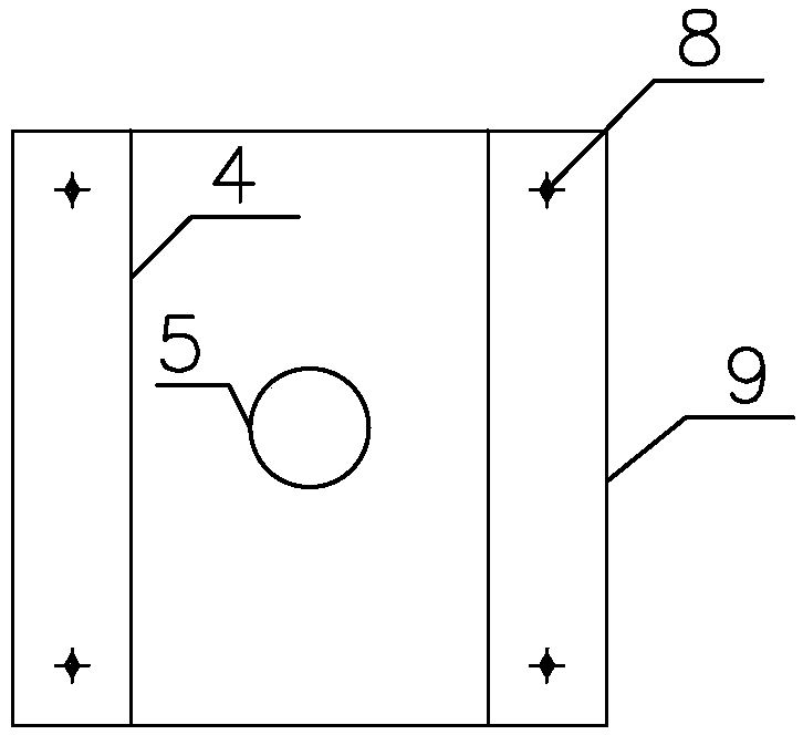
[0035] Such as Figure 1~3 As shown, it is a rear H-shaped steel cantilevered scaffold of the present invention, including a scaffold main body 12, steel pipe 5, H-shaped steel 4, steel wire rope 11, upper steel plate 7 and a pair of lower steel plates 9, 10, H-shaped steel 4 is arranged horizontally, H The lower flange 42 of the inner end of the shaped steel 4 is welded on the lower steel plate 9, and the lower steel plate 9 is connected with the existing concrete floor 1 of the lower floor through chemical bolts 8, so that the existing concrete floor 1 of the lower floor bears part of the force transmitted by the H-shaped steel; Existing wall 3 passes through to form a cantilever section, and the lower steel plate 10 is arranged on the bottom surface of the opening of the existing wall 3 for the H-shaped steel 4 to pass through, and the lower flange 42 of the part where the H-shaped steel 4 passes through the opening is pressed Tightly on this lower steel plate 10. The scaf...


PUM


Abstract

The invention discloses a rear H-shaped steel cantilever scaffold and a construction method thereof. The rear H-shaped steel cantilever scaffold comprises a scaffold main body, a steel pipe and H-shaped steel, wherein the H-shaped steel is horizontally arranged; a bottom flange at the inner end of the H-shaped steel is fixedly arranged on lower-layer existing concrete floor; the H-shaped steel outward penetrates out an existing wall body to form a cantilever section; the scaffold body is fixedly arranged on the cantilever section of the H-shaped steel; the steel pipe is erected between the upper-layer existing concrete floor and the lower-layer existing concrete floor; the upper end of the steel pipe is connected with the upper-layer existing concrete floor and the lower end of the steel pipe is connected with a top flange at the inner end of the H-shaped steel. Compared with a mode that the existing cantilever scaffolding is stressed by one-layer existing concrete floor, a mode of jointly bearing force by the upper-layer existing concrete floor and the lower-layer existing concrete floor, disclosed by the invention, has the advantages that the transmission path of force is changedand the damage to the floor can be reduced; in addition, the safety of the scaffold is improved; meanwhile, the limit requirements of size and strength of the floor on the cantilever scaffolding arereduced and the use range is wider.

Description

technical field [0001] The invention relates to a scaffold, in particular to a post-mounted H-shaped steel cantilevered scaffold, and also relates to a construction method of the rear-mounted H-shaped steel cantilevered scaffold. Background technique [0002] Scaffolding is a working platform set up to ensure the smooth progress of the construction process. At present, the construction of cantilevered scaffolds usually requires pre-embedded components on the floor. When building a scaffold on an existing building, since there are no pre-embedded components, post-installed components are required. The post-located components are mainly used on the existing floor. The method of drilling and embedding components. However, this approach has the following drawbacks: [0003] ⑴ Drilling holes to embed components on the existing floor, and the force of the existing concrete floor on the first floor will cause damage to the existing concrete floor. [0004] (2) The construction o...

Claims


Application Information

Patent Timeline
Patent Type & Authority Applications(China)
IPC IPC(8): E04G3/18E04G5/04
CPCE04G3/18E04G5/006E04G5/04E04G5/046
Inventor 吕文龙罗志靖隆敏马奎
Owner GUANGDONG PROVINCIAL ACAD OF BUILDING RES GRP CO LTD
Why Eureka
Try Eureka