

Automatic deashing device for diesel particle catcher
A particle trap and diesel technology, applied in the direction of mufflers, exhaust devices, machines/engines, etc., can solve the problems of time-consuming, waste of manpower, etc., and achieve the effects of ensuring accuracy, saving fuel, and saving regeneration costs
- Summary
- Abstract
- Description
- Claims
- Application Information
AI Technical Summary
Problems solved by technology
Method used
Image

Examples
Embodiment Construction
[0021] The present invention will be further described below in conjunction with the accompanying drawings and specific embodiments.
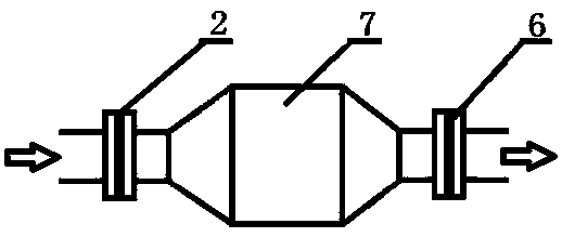
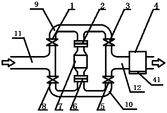
[0022] Please see attached figure 2 , an automatic ash removal device for a diesel particulate filter, comprising a first electric control valve 1, a second electric control valve 3, an ash collection box 4, a third electric control valve 5, a fourth solenoid valve 8, a first three-way Pipeline 9, the second three-way pipeline 10, the third three-way pipeline 11 and the fourth three-way pipeline 12; the three ends of the first three-way pipeline 9 are respectively connected with the first electric control valve 1, the first flange 2 and the The second electric control valve 3 is connected, and the three ends of the second three-way pipeline 10 are respectively connected with the fourth solenoid valve 8, the second flange 6 and the third electric control valve 5; the two ends of the third three-way pipeline 11 The ends are respectively connect...
PUM
 Abstract
Description
Claims
Application Information