Calibration platform of FBG sensor

A technology for calibrating platforms and fiber gratings, which is applied to instruments, optical devices, measuring devices, etc., can solve the problems of small ductility of fiber grating sensors, and it is not easy to stretch fiber grating sensors, and achieves easy operation, convenient measurement and operation. handy effect

Pending Publication Date: 2018-11-20
北京通为科技有限公司
View PDF0 Cites 2 Cited by
  • Summary
  • Abstract
  • Description
  • Claims
  • Application Information

AI Technical Summary

Problems solved by technology

[0005] However, the ductility of the fiber grating sensor is small, a

Method used


Image

  • Calibration platform of FBG sensor
  • Calibration platform of FBG sensor
  • Calibration platform of FBG sensor

Examples


Embodiment 1

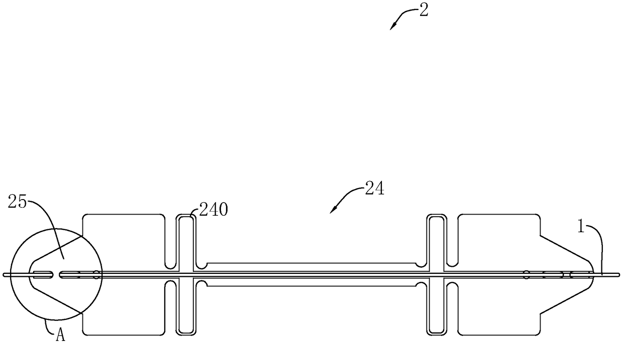
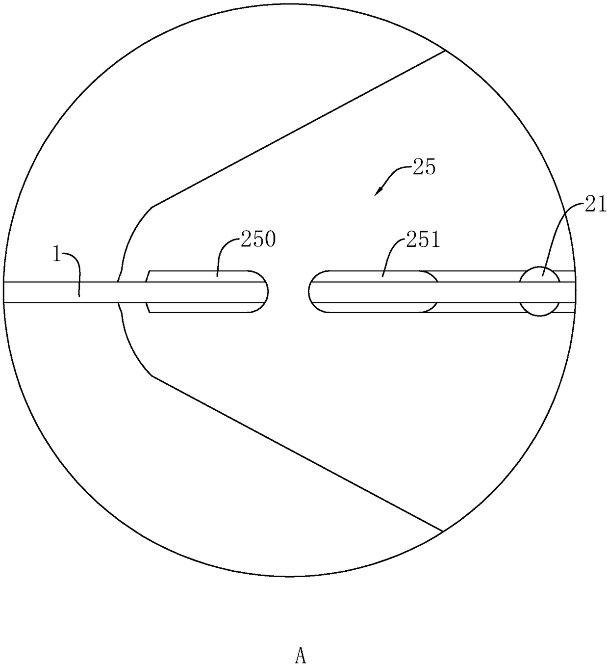
[0043] Embodiment 1, a kind of fiber grating sensor, with reference to figure 1 , figure 2 , including a frame for encapsulating the optical fiber 1 and the optical fiber 1 passing through the frame sheet 2, the frame can be set in a cylindrical shape, a flat shape or a cube shape, preferably a flat frame sheet 2 in this embodiment, a flat shape The frame piece 2 can be easily fixed or installed with the equipment under test. The optical fiber 1 inside the frame piece 2 is engraved with a grating. When the grating is deformed, the spectrum passing through the grating will be changed. After the optical fiber 1 enters the frame piece 2, a Reflection, forming reflection spectrum and refraction spectrum. By observing the changes of the two spectra, the deformation of the grating can be reflected. The grating is packaged on the frame sheet 2, and the frame sheet 2 is pasted on the device to be measured, and the slight deformation of the device can be felt. After the corresponding...


PUM


Abstract

The invention discloses a calibration platform of an FBG (Fiber Bragg Grating) sensor and relates to calibration of the FBG sensor. The key points of the technical scheme are that the calibration platform includes a calibration table, a fixed fixing table fixed on the calibration table, a movable fixing table connected to the calibration table in a sliding manner and having an upper surface beingcoplanar with the upper surface of the fixed fixing table, a stretching device used for adjusting the movable fixing table to be away from the fixed fixing table, and a distance measuring rule used for measuring the distance between the movable fixing table and the fixed fixing table, wherein the movable fixing table fits the fixed fixing table and abuts against the fixed fixing table and two endsof the FBG sensor are fixed on the movable fixing table and the fixed fixing table. According to the invention, the calibration platform has a characteristic of improving calibration precision through facilitating quantitative deformation of the FBG sensor.

Description

technical field [0001] The invention relates to the calibration of a fiber grating sensor, in particular to a calibration platform of a fiber grating sensor. Background technique [0002] Fiber Bragg grating sensor is a sensing process based on fiber Bragg grating. It obtains sensing information by modulating the fiber Bragg wavelength with external physical parameters. It is a wavelength-modulated fiber optic sensor. [0003] There is an existing fiber grating sensor, which includes a frame piece and an optical fiber with a grating passing through the frame piece. A welding groove is arranged on the frame piece. Place the optical fibers at both ends of the grating above the welding groove and fill the welding groove with solder to stretch the optical fiber. After changing the wavelength of the grating, the solder is heated and then cooled to complete the welding of the frame piece and the optical fiber, and complete the package. The optical fiber grating sensor encapsulate...

Claims


Application Information

Patent Timeline
IPC IPC(8): G01B11/16
CPCG01B11/165
Inventor 师振江葛薇徐希君
Owner 北京通为科技有限公司
Why Eureka
Try Eureka