Seismic migration imaging method and device

A seismic migration and imaging method technology, applied in the field of seismic exploration, can solve the problems of low migration imaging efficiency and poor imaging effect

Inactive Publication Date: 2018-11-20
CHINA UNIV OF MINING & TECH (BEIJING)
View PDF12 Cites 3 Cited by
  • Summary
  • Abstract
  • Description
  • Claims
  • Application Information

AI Technical Summary

Problems solved by technology

[0005] In view of this, the purpose of the present invention is to provide a seismic migration imaging method and d

Method used


Image

  • Seismic migration imaging method and device
  • Seismic migration imaging method and device
  • Seismic migration imaging method and device

Examples


Embodiment 1

[0058] According to an embodiment of the present invention, an embodiment of a seismic migration imaging method is provided. It should be noted that the steps shown in the flowcharts of the accompanying drawings can be executed in a computer system such as a set of computer-executable instructions, and , although a logical order is shown in the flowcharts, in some cases the steps shown or described may be performed in an order different from that shown or described herein.

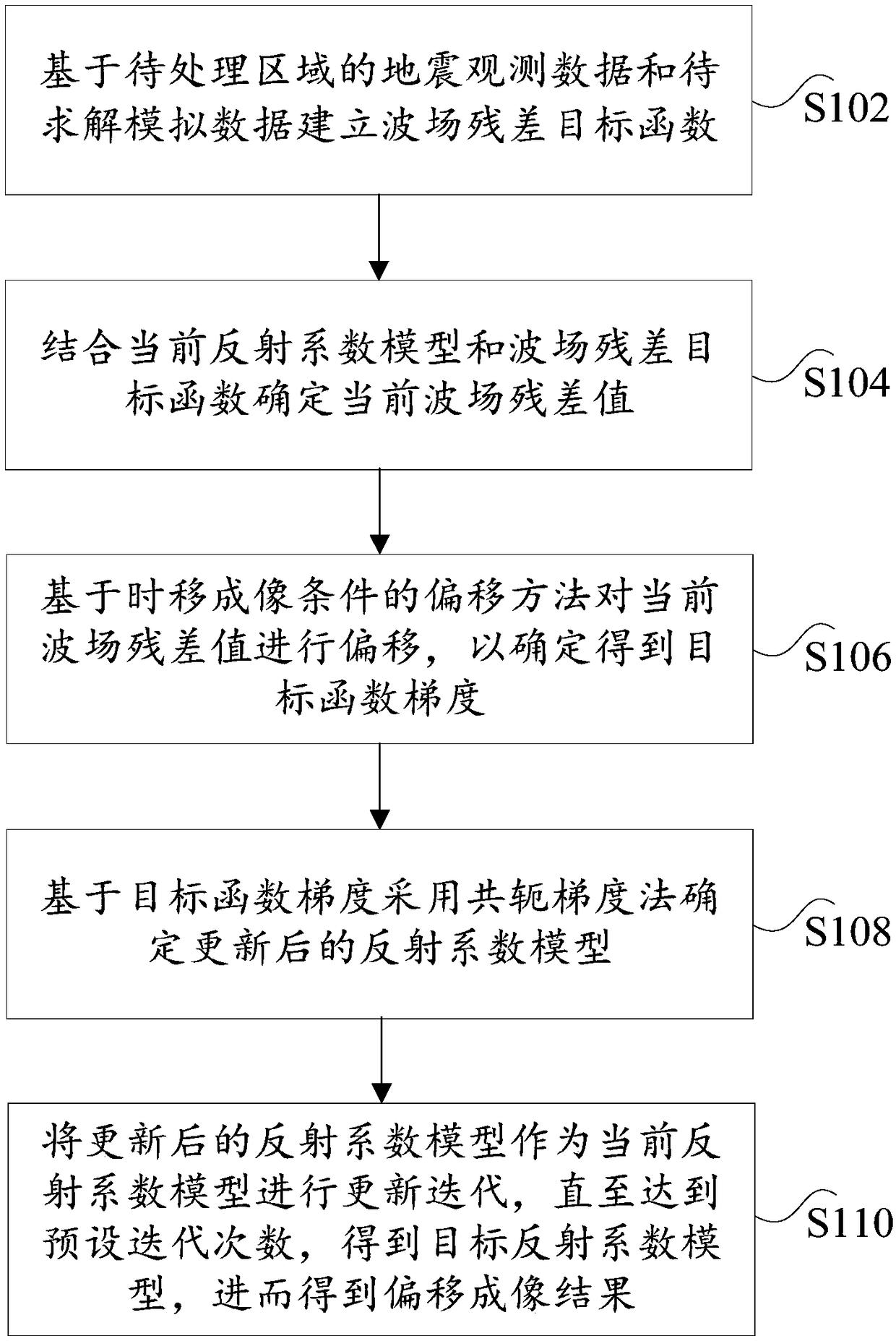
[0059] figure 1 is a flowchart of a seismic migration imaging method according to an embodiment of the present invention, such as figure 1 As shown, the method includes the following steps:

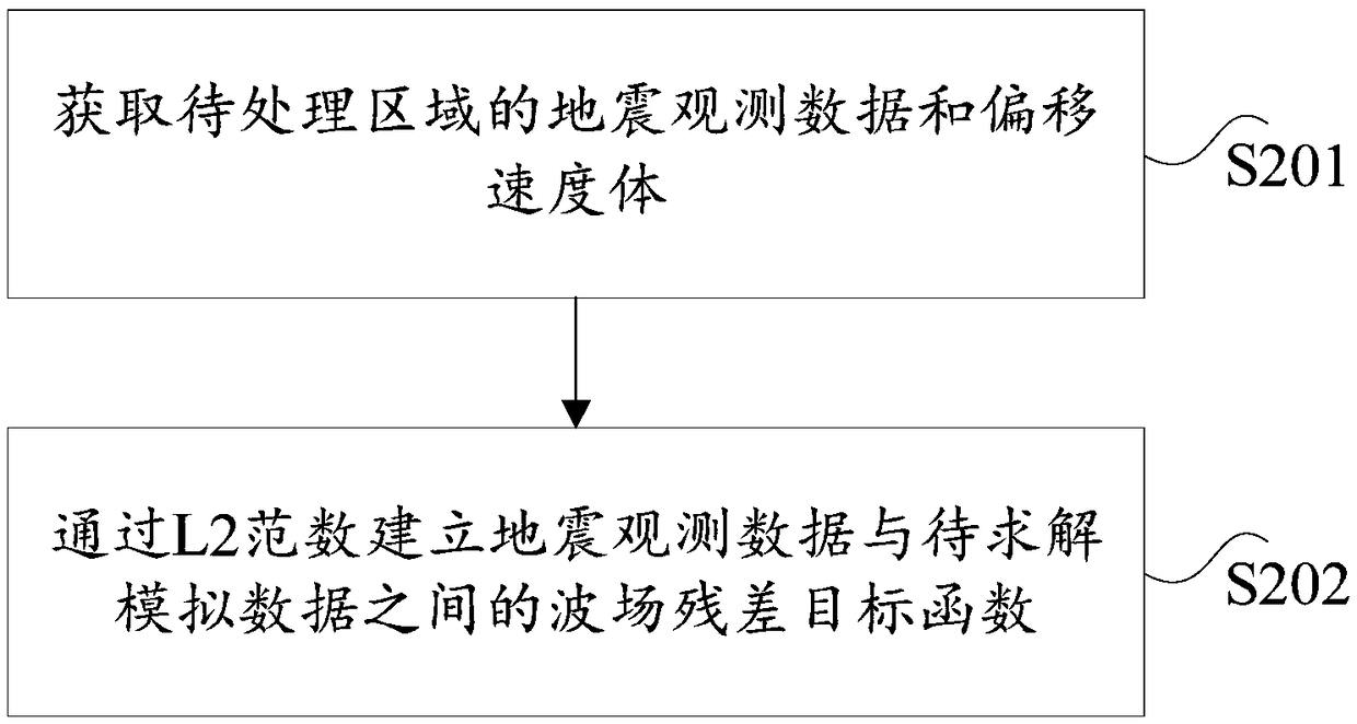
[0060] Step S102, establishing a wave field residual objective function based on the seismic observation data of the area to be processed and the simulated data to be solved;

[0061] In the embodiment of the present invention, the area to be processed is an area collected in the wild. Seismic observation data is t...

Embodiment 2

[0108] The embodiment of the present invention also provides a seismic migration imaging device, the seismic migration imaging device is mainly used to implement the seismic migration imaging method provided by the above content of the embodiment of the present invention, the seismic migration provided by the embodiment of the present invention is as follows The imaging device is introduced in detail.

[0109] Figure 7 is a schematic diagram of a seismic migration imaging device according to an embodiment of the present invention, such as Figure 7 As shown, the seismic migration imaging device mainly includes: an establishment module 11, a first determination module 12, a migration module 13, a second determination module 14 and an update iteration module 15, wherein:

[0110] Establishing a module for establishing a wave field residual objective function based on the seismic observation data of the area to be processed and the simulated data to be solved;

[0111] The fir...


PUM


Abstract

The invention provides a seismic migration imaging method and device, the method comprises the following steps: establishing a wave field residual target function based on the seismic observation dataand the analog data to be solved; determining the current wave field residual value in combination with the current reflection coefficient model and the wave field residual target function; the migration method based on time-shifted imaging condition migrates the residual value of the current wave field and obtains the gradient of the objective function; determining the updated reflection coefficient model by adopting a conjugate gradient method based on the target function gradient; carrying out updating iteration on the updated reflection coefficient model, which is used as a current reflection coefficient model until the preset iteration number is reached. The target reflection coefficient model is obtained, and then the migration imaging results are obtained. The method adopts the least squares method, the accuracy of the seismic migration imaging is effectively improved, the imaging effect is good, time-shifted imaging conditions are used in the migration imaging process, the calculation amount is small, the migration imaging efficiency is improved, technical problems of low efficiency and poor imaging effect of traditional migration imaging is solved.

Description

technical field [0001] The invention relates to the technical field of seismic exploration, in particular to a seismic migration imaging method and device. Background technique [0002] Seismic exploration method is an important means for humans to obtain underground space information, among which seismic migration imaging is a key step in seismic data processing. Migration can make the reflected wave return to its original position accurately and the diffracted wave converge, so as to visually show the true shape of the underground structure. [0003] At present, the traditional migration imaging technology generally adopts the seismic imaging theory under the single-point scattering approximation, which is mainly based on the matching analysis of the source wave field and the receiver point wave field. Reverse continuation, and then apply appropriate imaging conditions to image the reflective surface. Appropriate imaging conditions have an important impact on migration v...

Claims


Application Information

Patent Timeline
IPC IPC(8): G01V1/28
CPCG01V1/28
Inventor 林朋彭苏萍赵惊涛崔晓芹
Owner CHINA UNIV OF MINING & TECH (BEIJING)
Why Eureka
Try Eureka