Control method for constant power of PTC heating assembly

A heating component, constant power technology, applied in electric heating devices, electrical components, ohmic resistance heating, etc., can solve the problems of room temperature resistivity drop, power uncontrollable, resistivity increase, etc., to achieve good protection, easy to control power. Effect

Inactive Publication Date: 2018-11-20
浙江欧兰顿电器科技有限公司
View PDF5 Cites 0 Cited by
  • Summary
  • Abstract
  • Description
  • Claims
  • Application Information

AI Technical Summary

Problems solved by technology

Usually the PTC we refer to refers to the positive temperature coefficient thermistor, referred to as PTC thermistor, PTC is a positive temperature coefficient thermal material, which has the characteristic that the resistivity increases with the increase of temperature. In 1955, Philips of the Netherlands Heyman et al. found that after adding a trace amount of rare earth elements to ceramics, its room temperature resistivity dropped significantly, and its resistivity could increase by more than three orders of magnitude in a narrow temperature range. They first discovered the characteristics of PTC materials. , For more than 40 years, the research on PTC materials has made a major breakthrough. The theory of PTC materials is becoming more and more mature, and the scope of application is also expanding. PTC heating components are a kind of high-efficiency heating equipment produced by PTC materials. However, the existing PTC heating components cannot be controlled when the power changes during heating, and when the power is too large, the heat generation is too large and the temperature is too high, which is easy to cause damage to the PTC heating components. Therefore, a constant power control method for PTC heating components is proposed.

Method used


Image

  • Control method for constant power of PTC heating assembly
  • Control method for constant power of PTC heating assembly

Examples


Embodiment Construction

[0021] The following will clearly and completely describe the technical solutions in the embodiments of the present invention with reference to the accompanying drawings in the embodiments of the present invention. Obviously, the described embodiments are only some, not all, embodiments of the present invention.

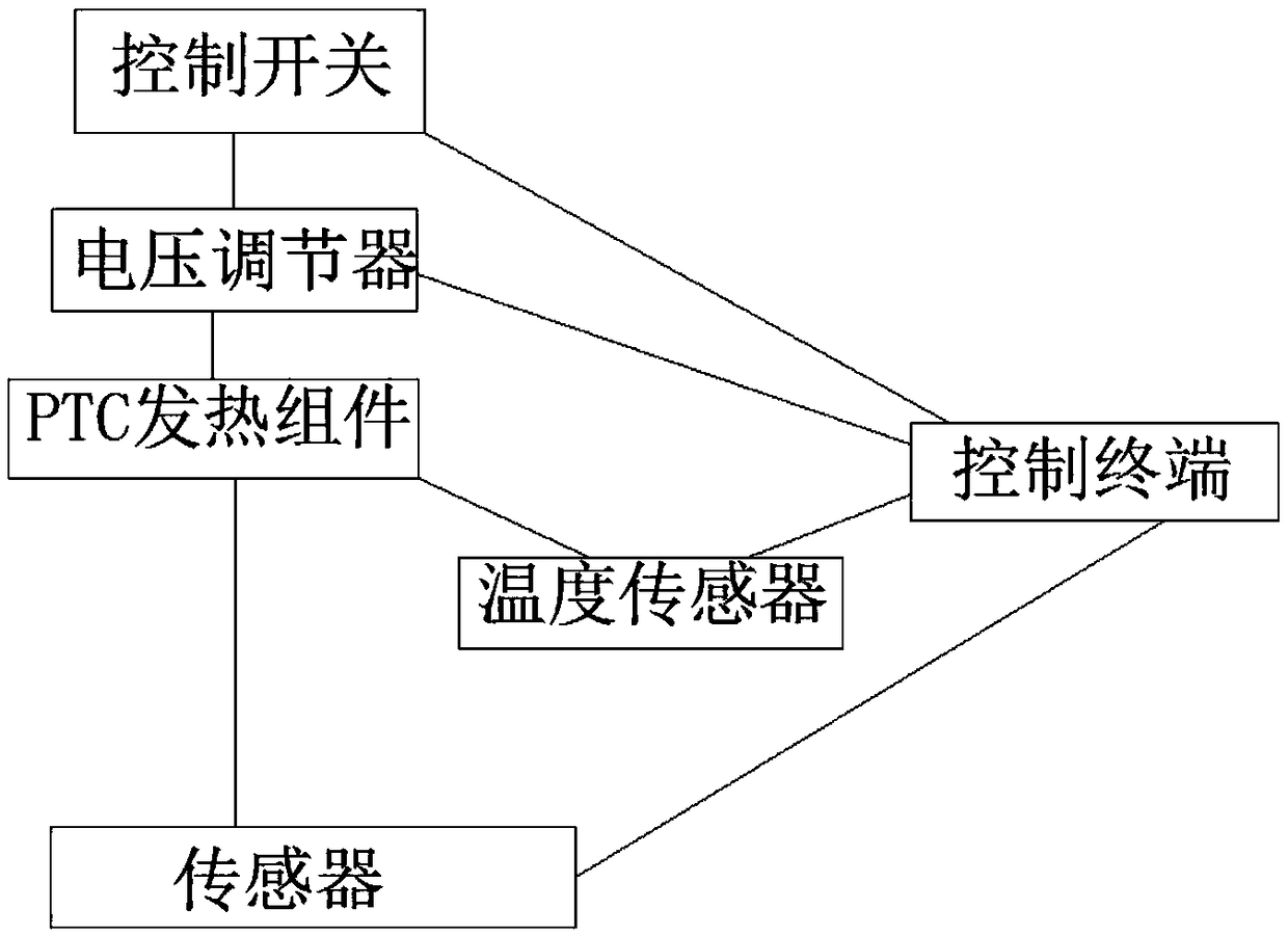
[0022] refer to Figure 1-2 , a method for controlling constant power of a PTC heating component, comprising the following steps:

[0023] S1: Control switch, used to control the switch of the PTC heating component, connect the control switch to the PTC heating component through a wire;

[0024] S2: voltage regulator, the voltage regulator can be used to adjust the circuit voltage;

[0025] S3: PTC heating component, the PTC heating component is connected to the power supply through the wire, and the PTC heating component can be started to generate heat through the control switch;

[0026] S4: sensor, the current and voltage in the circuit can be detected at any ti...


PUM


Abstract

The invention discloses a control method for constant power of a PTC heating assembly. According to the control method, a control switch is used for controlling opening and closing of the PTC heatingassembly; the control switch is connected with the PTC heating assembly through a wire; a voltage regulator can be used for adjusting circuit voltage; and the PTC heating assembly is connected with apower supply through a wire. By means of the control switch, opening and closing of the PTC heating assembly circuit can be controlled; the magnitude of the current and voltage in the power supply circuit can be monitored in real time through a current sensor and a voltage sensor which are arranged, and the acquired information can be transmitted to a control terminal; and through the control of the control terminal, the voltage of the circuit is changed through the set voltage regulator, so that the magnitude the voltage and the current can be adjusted in time according to the demand change,the voltage and the current are in a relatively stable state, and power invariability can be controlled conveniently.

Description

technical field [0001] The invention relates to the technical field of PTC heating components, in particular to a method for controlling constant power of a PTC heating component. Background technique [0002] PTC generally refers to semiconductor materials or components with a large positive temperature coefficient. Usually the PTC we refer to refers to the positive temperature coefficient thermistor, referred to as PTC thermistor, PTC is a positive temperature coefficient thermal material, which has the characteristic that the resistivity increases with the increase of temperature. In 1955, Philips of the Netherlands Heyman et al. found that after adding a trace amount of rare earth elements to ceramics, its room temperature resistivity dropped significantly, and its resistivity could increase by more than three orders of magnitude in a narrow temperature range. They first discovered the characteristics of PTC materials. , For more than 40 years, the research on PTC mater...

Claims


Application Information

Patent Timeline
IPC IPC(8): H05B1/02H05B3/00
CPCH05B1/0202H05B3/00
Inventor 茅晓晨
Owner 浙江欧兰顿电器科技有限公司
Why Eureka
Try Eureka