
Printing ink raw material pre-mixing device

A pre-mixing and raw material technology, applied in mixers, fluid mixers, transportation and packaging, etc., can solve the problems of poor mixing effect and long mixing time, and achieve the effect of improving mixing effect and reducing mixing time.

Inactive Publication Date: 2018-11-23
安徽雅美油墨有限公司
View PDF0 Cites 7 Cited by
  • Summary
  • Abstract
  • Description
  • Claims
  • Application Information

AI Technical Summary

Problems solved by technology

At present, there are various mixing equipments on the market, but basically all kinds of raw materials are directly poured into the mixing tank for mixing, which takes a long time and has poor mixing effect.

Method used


Image

  • Printing ink raw material pre-mixing device
  • Printing ink raw material pre-mixing device

Examples


Embodiment 1

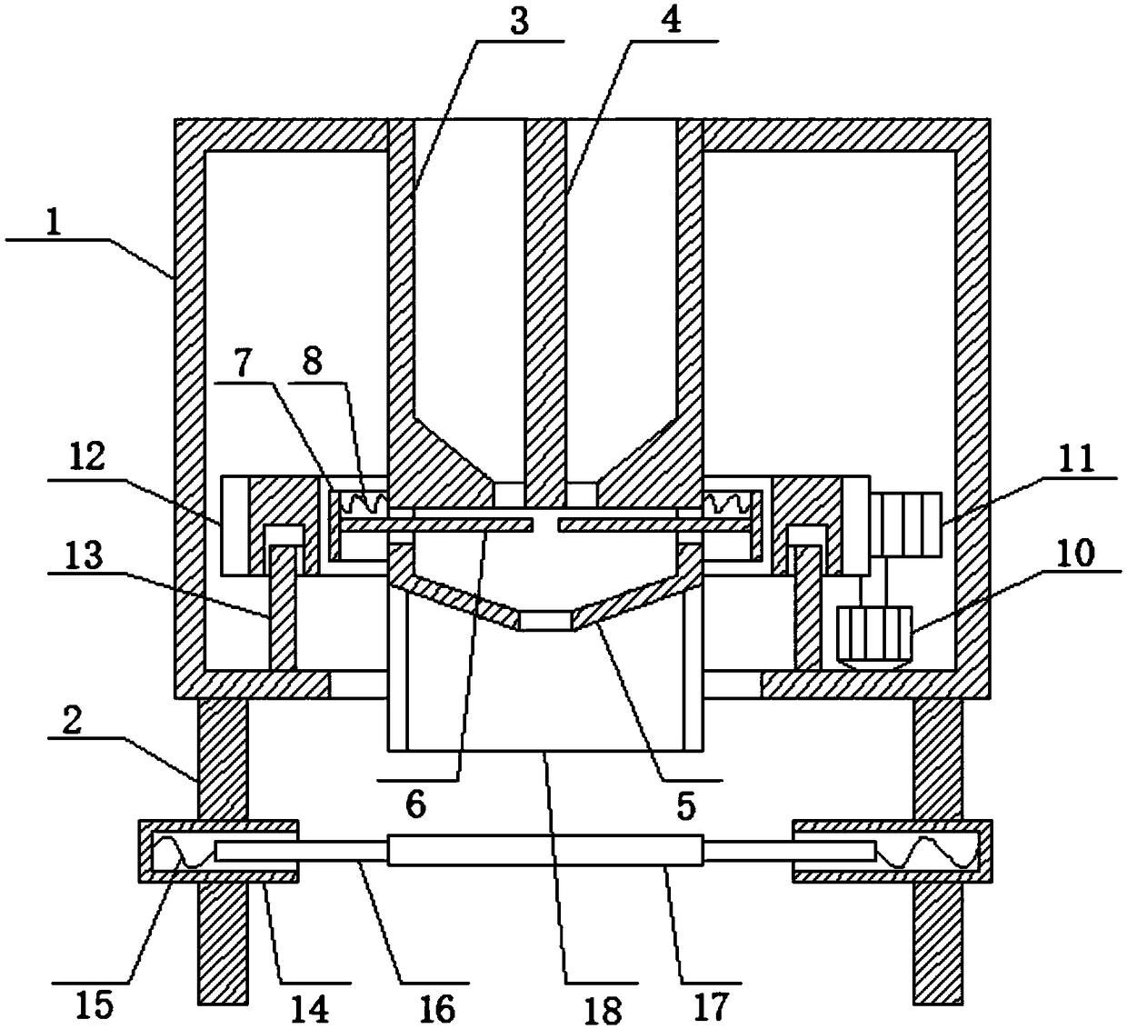
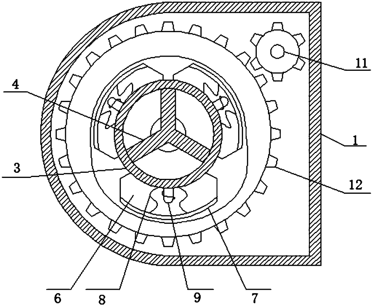
[0023] Such as Figure 1-2 As shown, a premixing device for ink raw materials includes a housing 1, the bottom wall of the housing 1 is provided with a first discharge port, the lower end of the housing 1 is connected with two supporting legs 2, and the upper wall of the housing 1 A cylinder 3 is fixedly inserted in the middle, and the cylinder 3 is located directly above the first discharge port. The height around the inner bottom wall of the cylinder 3 is higher than the height of the center point. The plate 4 divides the cylinder 3 into three chambers, the bottom wall of the chamber is provided with a second outlet, the bottom wall of the cylinder 3 is connected with a hopper 5, and the hopper 5 is provided with three chambers matching the chamber. The baffle 6, one end of the baffle 6 moves through the side wall of the hopper 5 and is connected with an arc-shaped iron plate 7, and a first spring 8 is connected between the side wall of the arc-shaped iron plate 7 and the ou...

Embodiment 2

[0027] Such as Figure 1-2 As shown, a premixing device for ink raw materials includes a housing 1, the bottom wall of the housing 1 is provided with a first discharge port, the lower end of the housing 1 is connected with two supporting legs 2, and the upper wall of the housing 1 A cylinder 3 is fixedly inserted in the middle, and the cylinder 3 is located directly above the first discharge port. The height around the inner bottom wall of the cylinder 3 is higher than the height of the center point. The plate 4 divides the cylinder 3 into three chambers, the inner bottom wall of the chamber is provided with a second outlet, the bottom wall of the cylinder 3 is connected with a hopper 5, and the hopper 5 is provided with three chambers matching the chamber. A baffle 6, one end of the baffle 6 moves through the side wall of the hopper 5 and is connected with an arc-shaped iron plate 7, and a first spring is connected between the side wall of the arc-shaped iron plate 7 and the ...


PUM


Abstract

The invention relates to the technical field of printing ink production, in particular to a printing ink raw material pre-mixing device. The printing ink raw material pre-mixing device comprises an enclosure, wherein the bottom wall of the enclosure is provided with a first discharge outlet, the lower end of the enclosure is connected with two supporting legs, the upper wall of the enclosure is fixedly spliced with a barrel, the barrel is arranged above the first discharge outlet, the inner side wall of the barrel is connected with a partition plate, the partition plate divides the barrel intothree cavities, the bottom wall of each of the cavities is provided with a second discharge outlet, the bottom wall of the barrel is connected with a bucket, three baffles matching the cavities are arranged in the bucket, and one end of each of the baffles movably penetrates through the side wall of the bucket and is connected with an arc iron plate. An arc notch of a second gear in the printingink raw material pre-mixing device can be rotated to different arc iron plates to open the second discharge outlet of each of the cavities to drop different printing ink raw materials in a periodicalway and layer the printing ink raw materials to pre-mix the printing ink raw materials to reduce mixing time of mixing equipment while enhancing mixing effects.

Description

technical field [0001] The invention relates to the technical field of ink production, in particular to an ink raw material premixing device. Background technique [0002] Ink is an important material for printing. It expresses patterns and characters on the substrate by printing or inkjet painting. Ink is composed of linking material (resin), pigment, filler, additives and solvent, etc., which are uniformly mixed and rolled repeatedly to form a viscous colloidal fluid. [0003] In the production process of the ink, after the formula is determined, the pigments, binders and additives are quantitatively weighed, put into the mixer for stirring, and the wetting and preliminary dispersion processing are completed. At present, there are various mixing equipments on the market, but basically all kinds of raw materials are directly poured into the mixing bucket for mixing, which takes a long time and has poor mixing effect. [0004] Therefore, a pre-mixing device for ink raw mat...

Claims


Application Information

Patent Timeline
Patent Type & Authority Applications(China)
IPC IPC(8): B01F5/00
CPCB01F25/00B01F2025/919B01F2101/35
Inventor 耿益祥
Owner 安徽雅美油墨有限公司
Learn More