Storage battery separating and breaking device
A crushing device and battery technology, which is applied in battery recycling, recycling technology, waste collector recycling, etc., can solve the problems of low processing efficiency, poor sealing of the device, and the inability to crush and separate lead-acid batteries at the same time, so as to improve processing efficiency , good sealing effect
- Summary
- Abstract
- Description
- Claims
- Application Information
AI Technical Summary
Problems solved by technology
Method used
Image

Examples
Embodiment 1
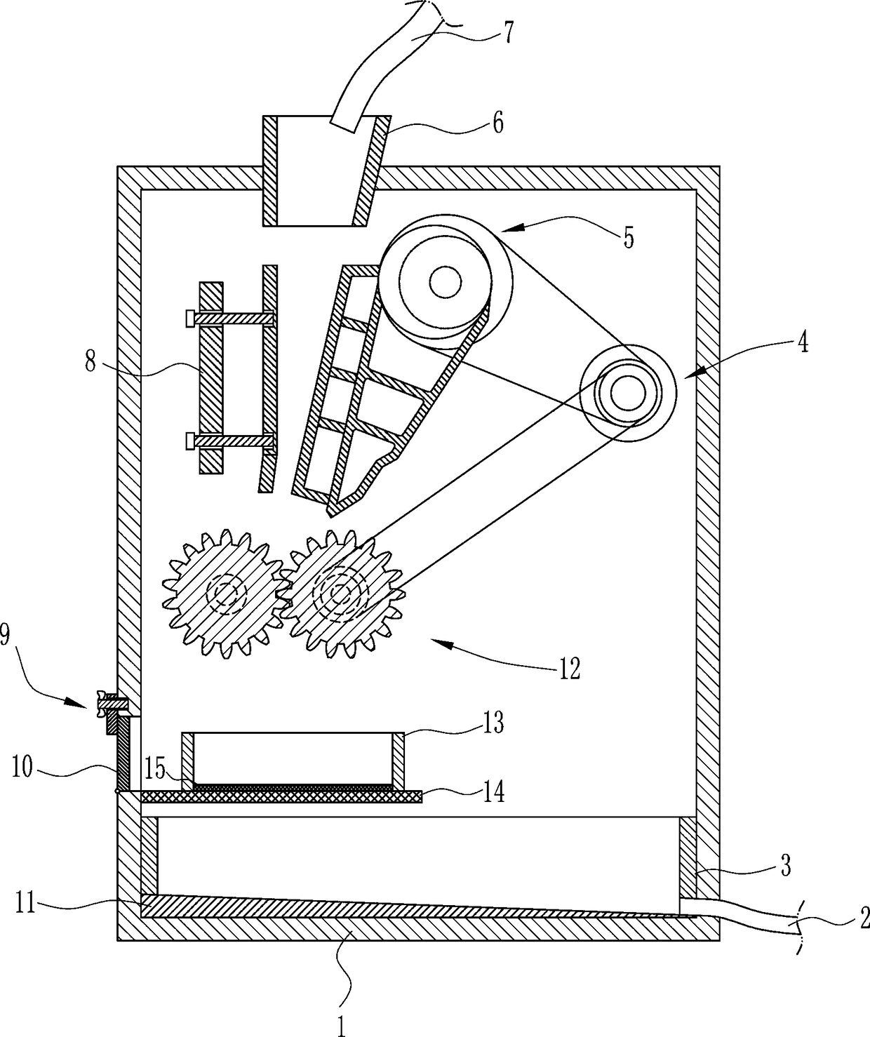
[0026] A storage battery separation and crushing device, such as Figure 1-6 As shown, it includes installation box 1, discharge pipe 2, first collection frame 3, drive mechanism 4, crushing mechanism 5, feed frame 6, flushing pipe 7, installation plate 8, fixing mechanism 9, cover plate 10, inclined Plate 11, grinding mechanism 12, second collection frame 13, first net plate 14 and second net plate 15; the first collection frame 3 is affixed to the inner bottom of the installation box 1, and the inclined plate 11 is affixed to the first collection frame 3 Bottom; the discharge pipe 2 is fixed to one side of the first collection frame 3, and extends through the installation box 1 to the outside; the driving mechanism 4 is fixed to the inner rear wall of the installation box 1, and the feeding frame 6 is fixed to the installation box 1 At the top, the flushing pipe 7 is fixedly connected to the feed frame 6; the installation plate 8 is fixedly connected to the installation box ...
Embodiment 2
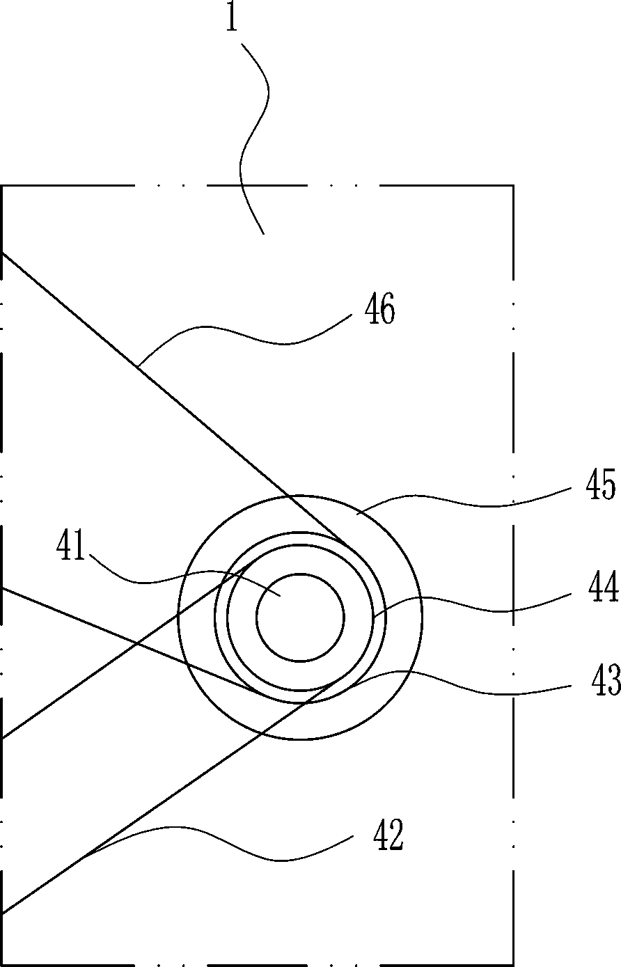
[0029]This embodiment is similar to Embodiment 1, further, the driving mechanism 4 includes a first rotating shaft 41, a first flat belt 42, a first pulley 43, a second pulley 44, a motor 45 and a second flat belt 46; the motor 45 is fixed Connected to the rear wall of the installation box 1, one end of the first rotating shaft 41 is pivotally connected to the output end of the motor 45; the first pulley 43 and the second pulley 44 are fixedly connected to the first rotating shaft 41, and the distance from the first pulley 43 to the motor 45 is less than The distance from the second pulley 44 to the motor 45; the first pulley 43 is connected to the crushing mechanism 5 through the second flat belt 46, and the second pulley 44 is connected to the grinding mechanism 12 through the first flat belt 42; During processing, the motor 45 is controlled to rotate counterclockwise, the motor 45 drives the first rotating shaft 41 to rotate counterclockwise, the first rotating shaft 41 driv...
Embodiment 3
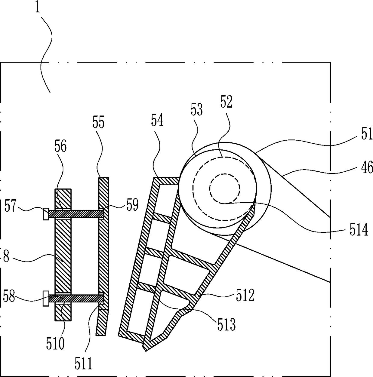
[0031] This embodiment is similar to Embodiment 1. Further, the crushing mechanism 5 includes a third pulley 51, a first bearing seat 52, a third rotating shaft 53, a first crushing platen 54, a second crushing platen 55, a first screw rod 57, The second screw rod 58, the support frame 512, the connecting rod 513 and the second rotating shaft 514; the first bearing seat 52 is fixedly connected to the inner rear wall of the installation box 1; part and the third pulley 51; the third pulley 51 is connected with the first pulley 43 through the second flat belt 46; the third rotating shaft 53 is fixed with the eccentric position of the third pulley 51; Then, the first crushing platen 54 is fixedly connected to the support frame 512 through the connecting rod 513, the mounting plate 8 is provided with a first threaded hole 56 and a third threaded hole 510, and the second crushing platen 55 is provided with a The second threaded hole 59, the fourth threaded hole 511; the first threa...
PUM
 Abstract
Description
Claims
Application Information
 - R&D
- Intellectual Property
- Life Sciences
- Materials
- Tech Scout
- Unparalleled Data Quality
- Higher Quality Content
- 60% Fewer Hallucinations
Browse by: Latest US Patents, China's latest patents, Technical Efficacy Thesaurus, Application Domain, Technology Topic, Popular Technical Reports.
© 2025 PatSnap. All rights reserved.Legal|Privacy policy|Modern Slavery Act Transparency Statement|Sitemap|About US| Contact US: help@patsnap.com