Al technical title is built by PatSnap Al team. It summarizes the technical point description of the patent document.
A technology of color coating and spraying equipment, applied in the direction of spraying equipment, etc., can solve the problems of uncoatable workpiece spraying, affecting personal health, high use limitations, etc., to achieve the effect of reducing contact area, reducing use limitations, and reducing manpower
Inactive Publication Date: 2018-11-23
江苏嘉鑫新材料科技有限公司
View PDF0 Cites 9 Cited by
Summary
Abstract
Description
Claims
Application Information
AI Technical Summary
This helps you quickly interpret patents by identifying the three key elements:
Problems solved by technology
Method used
Benefits of technology
Problems solved by technology
[0002] As we all know, the spraying device for polyurethane color coating is an auxiliary device for spraying polyurethane exterior coatings to better meet customer needs. It has been widely used in the field of polyurethane energy-saving board production; now Some spraying devices for polyurethane color coatings include a spraying box, a working chamber is arranged inside the spraying box, and an operating port is arranged at the front end of the spraying box, the operating port communicates with the inside of the working chamber, and a spray gun is arranged inside the working chamber; the existing polyurethane When the color coating is used with a spraying device, first place the coating workpiece to be sprayed inside the spray chamber, and then manually spray the blended paint on the coating workpiece through a spray gun; the existing polyurethane color coating is used for spraying During the use of the device, it was found that manual contact with the paint for a long time affects personal health, and at the same time wastes more manpower, resulting in lower reliability in use; and the coated workpiece is directly attached to the inner wall of the bottom of the spray chamber, which cannot be well treated. Coated workpieces are fully sprayed, resulting in relatively limited use
Method used
Image
Click on the blue label to locate the original text in one second.
Reading with bidirectional positioning of images and text.
Examples
Embodiment Construction
[0021] The specific implementation manners of the present invention will be further described in detail below in conjunction with the accompanying drawings and embodiments. The following examples are used to illustrate the present invention, but are not intended to limit the scope of the present invention.
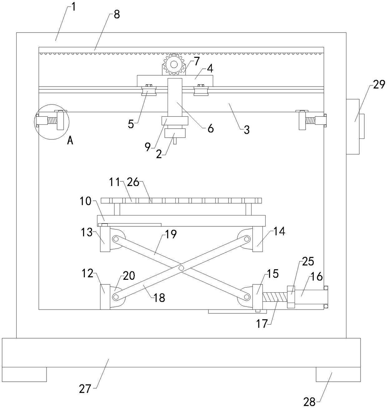
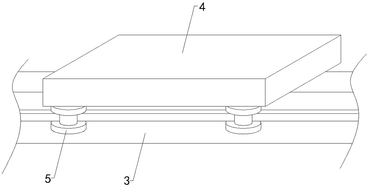
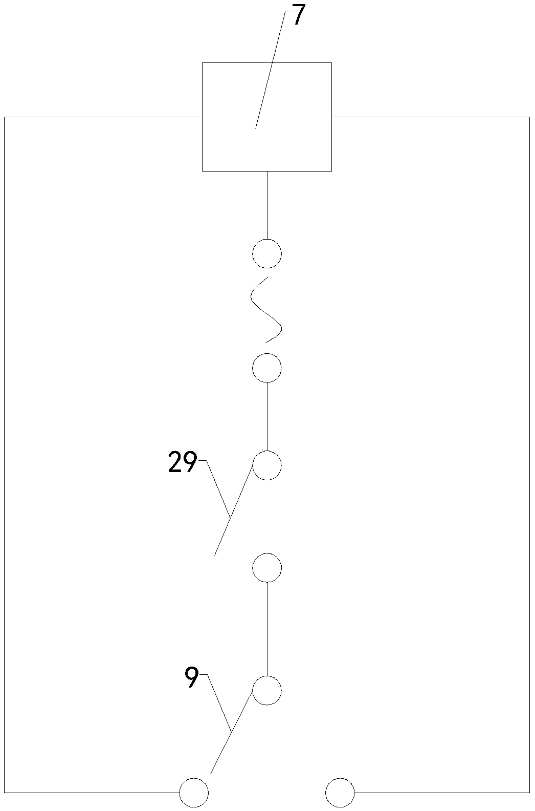
[0022] Such as Figure 1 to Figure 5As shown, a kind of spraying device for polyurethane color coating of the present invention comprises a spraying box 1, a working chamber is arranged inside the spraying box, and an operating port is arranged at the front end of the spraying box, the operating port communicates with the inside of the working chamber, and the inside of the working chamber A spray gun 2 is provided; including a support beam 3, a slide plate 4, two groups of front pulleys 5, two groups of rear pulleys, a front connection plate 6, a rear connection plate, a gear motor 7, a gear rail 8 and a travel switch 9, the left end of the support beam and The right end...
PUM
Abstract
The invention relates to the technical field of polyurethane energy-saving plate production accessory devices, in particular to a spraying device for a polyurethane colored coating. The spraying device can realize automatic spraying, contact time of people and the coating is reduced, impact of coating on personal health is reduced, manpower is reduced, and using reliability is improved; a coatingworkpiece can be well sprayed, so that contact area of the bottom end of the coating workpiece and the inner wall of the bottom end of a spraying cavity is reduced, and using limitation is lowered. The spraying device comprises a spraying box, a working cavity is arranged inside the spraying box, an operation port is arranged at the front end of the spraying box, and a spraying gun is arranged inside the working cavity; the spraying device further comprises a supporting beam, a sliding plate, two front pulleys, two rear pulleys, a front connecting plate, a rear connecting plate, a gear motor,a toothed rail and a stroke switch; the spraying device further comprises a placement plate, a supporting plate, a left fixed plate, a left moving plate, a right fixed plate, a right moving plate, anadjusting threaded pipe, an adjusting threaded rod, a first supporting rod and a second supporting rod, and four support rods are arranged at the bottom end of the supporting plate.
Description
technical field [0001] The invention relates to the technical field of an auxiliary device for producing polyurethane energy-saving boards, in particular to a spraying device for polyurethane color coating. Background technique [0002] As we all know, the spraying device for polyurethane color coating is an auxiliary device for spraying polyurethane exterior coatings to better meet customer needs. It has been widely used in the field of polyurethane energy-saving board production; now Some spraying devices for polyurethane color coatings include a spraying box, a working chamber is arranged inside the spraying box, and an operating port is arranged at the front end of the spraying box, the operating port communicates with the inside of the working chamber, and a spray gun is arranged inside the working chamber; the existing polyurethane When the color coating is used with a spraying device, first place the coating workpiece to be sprayed inside the spray chamber, and then m...
Claims
Application Information
Patent Timeline
Application Date:The date an application was filed.
Publication Date:The date a patent or application was officially published.
First Publication Date:The earliest publication date of a patent with the same application number.
Issue Date:Publication date of the patent grant document.
PCT Entry Date:The Entry date of PCT National Phase.
Estimated Expiry Date:The statutory expiry date of a patent right according to the Patent Law, and it is the longest term of protection that the patent right can achieve without the termination of the patent right due to other reasons(Term extension factor has been taken into account ).
Invalid Date:Actual expiry date is based on effective date or publication date of legal transaction data of invalid patent.