Wood line groove paint coating mechanism for coating machine

A technology of wood molding and brushing machine, which is applied in the direction of coating and surface coating liquid device, etc., which can solve the problems of reduced coating effect of wood molding, good brushing effect, and high brushing efficiency, so as to achieve good brushing effect, improvement of adsorption effect, effect of improvement of brushing effect

Active Publication Date: 2018-11-23
湖州亨力木业有限公司
View PDF9 Cites 0 Cited by
  • Summary
  • Abstract
  • Description
  • Claims
  • Application Information

AI Technical Summary

Problems solved by technology

[0002] At present, in order to have good aesthetics, the wood moldings on the market often need to open grooves with different cross-sectional shapes on the surface; but because most of the conventional painting devices can only paint the plane, they cannot be applied to the grooves of the wood moldings. Due to the coating work, the manufacturers need to use manual coating or mechanical spraying to complete the coating of the grooves of the wood strips.
However, the manual coating method will not only reduce the painting efficiency and increase the labor cost, but also cause uneven thickness of the paint surface during the painting process, thereby reducing the painting effect of the wood strips; and mechanical spraying Although the method can improve the coating efficiency of the wood moldings and the uniformity of the paint film, it needs to consume a lot of paint during the spraying process, and the grooves located on the bottom of the wood moldings will slide down with the condensation of the paint after spraying to form different shapes. The protrusions, resulting in an increase in processing costs and a reduction in the coating effect of the wood strips
Therefore, the existing brushing methods for the grooves of wooden moldings cannot simultaneously have the characteristics of high brushing efficiency, low processing cost and good brushing effect

Method used


Image

  • Wood line groove paint coating mechanism for coating machine

Examples


Embodiment Construction

[0011] The present invention will be further described below in conjunction with the accompanying drawings and embodiments, but not as a basis for limiting the present invention.

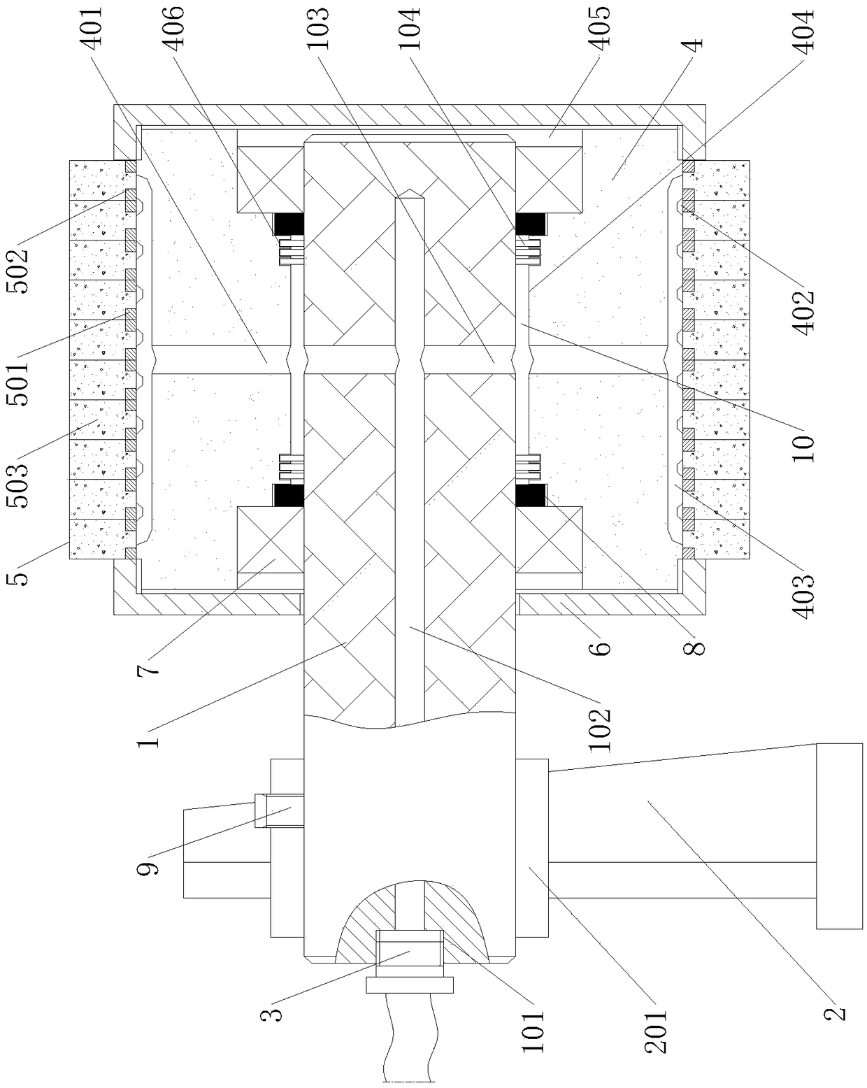
[0012] Example. A wood strip groove painting mechanism for a brushing machine, which is composed of figure 1 As shown, including the installation shaft 1, the outer side of the installation shaft 1 is connected with a fixed bracket 2, and the middle part of one end of the installation shaft 1 is provided with a thread groove 101 and a blind hole 102 sequentially from the outside to the inside, and the thread groove 101 is connected with a paint inlet pipe 3, blind On both sides of the hole 102, there are first paint inlet holes 103 that pass through the installation shaft 1. The end of the installation shaft 1 away from the threaded groove 101 is connected to a rotatable cylinder 4, and the middle part of the cylinder 4 is circularly distributed with multiple second paint inlet holes. 401, the oute...


PUM


Abstract

The invention discloses a wood line groove paint coating mechanism for a coating machine. The wood line groove paint coating mechanism for the coating machine comprises a mounting shaft; the outer side of the mounting shaft is connected with a fixed bracket; a threaded groove and a blind hole are formed in the middle part of one end of the mounting shaft from outside to inside; the internal part of the threaded groove is connected with a paint inlet pipe; first paint inlet holes which run through the mounting shaft are formed in the two sides of the blind hole; one end, far away from the threaded groove, of the mounting shaft is connected with a rotatable cylinder; a plurality of paint inlet holes are distributed in the middle part of the cylinder annularly; a plurality of arc-shaped grooves are distributed in the outer surface of the cylinder at intervals; the plurality of arc-shaped grooves are connected mutually through a plurality of arc-shaped cross grooves; the middle parts of the arc-shaped cross grooves and the second paint inlet holes are mutually communicated; a plurality of annular sponge brushes are arranged on the outer side of the cylinder in parallel; and clamping sleeves which are in threaded connection with the cylinder are arranged on the two sides of the annular sponge brushes respectively. The wood line groove paint coating mechanism for the coating machinehas the characteristics of high coating efficiency, low processing cost and good coating effect.

Description

technical field [0001] The invention relates to a wood strip painting machine, in particular to a wood strip groove painting mechanism for the painting machine. Background technique [0002] At present, in order to have good aesthetics, the wood moldings on the market often need to open grooves with different cross-sectional shapes on the surface; but because most of the conventional painting devices can only paint the plane, they cannot be applied to the grooves of the wood moldings. As a result, manufacturers need to manually coat or mechanically spray when coating the grooves of the wood strips. However, the manual coating method will not only reduce the painting efficiency and increase the labor cost, but also cause uneven thickness of the paint surface during the painting process, thereby reducing the painting effect of the wood strips; and mechanical spraying Although the method can improve the coating efficiency of the wood moldings and the uniformity of the paint fi...

Claims


Application Information

Patent Timeline
Patent Type & Authority Applications(China)
IPC IPC(8): B05C5/02B05C11/10
CPCB05C5/02B05C11/1039
Inventor 徐启旺
Owner 湖州亨力木业有限公司
Why Eureka
Try Eureka