Polisher discharge rack with baffle plate

A technology of polishing machine and material rack, which is applied in the direction of grinding frame, grinding slide, grinding bed, etc., and can solve the problems that the quantity of discharged products cannot be calculated, the height of the discharge rack cannot be adjusted, and there is no protective device. , to achieve the effect of good loss prevention and transmission, good output and transmission effect, and convenient operation

Inactive Publication Date: 2018-11-23
单伟民
View PDF0 Cites 0 Cited by
  • Summary
  • Abstract
  • Description
  • Claims
  • Application Information

AI Technical Summary

Problems solved by technology

The former requires the use of coarser abrasives to ensure a greater polishing rate to remove the polished damage layer, but the polishing damage layer is also deeper, while the latter requires the use of the finest materials to make the polishing damage layer shallower, but the polishing damage layer is also deeper. low rate
In the process of polishing, a discharge rack is needed to accept and transport the polished objects, so as to avoid the problem that the objects cannot be placed. However, the traditional discharge rack is manually operated, and no effective protective device is installed. The finished product is prone to problems
[0003] There are certain disadvantages in the use of the existing discharge rack of the polishing machine. First, when the ejecting mechanism is in direct contact with the material, it is easy to cause damage to the material and reduce the production quality of the product. Secondly, there is no protective device, and the output product Falling down is easy to cause surface wear, and it is impossible to calculate the quantity of discharged products. At the same time, it is impossible to effectively adjust the height of the discharge rack, which has brought a certain impact in the process of use. For this reason, we propose a Polisher outfeed rack for plates

Method used


Image

  • Polisher discharge rack with baffle plate
  • Polisher discharge rack with baffle plate
  • Polisher discharge rack with baffle plate

Examples


Embodiment Construction

[0017] In order to make the technical means, creative features, goals and effects achieved by the present invention easy to understand, the present invention will be further described below in conjunction with specific embodiments.

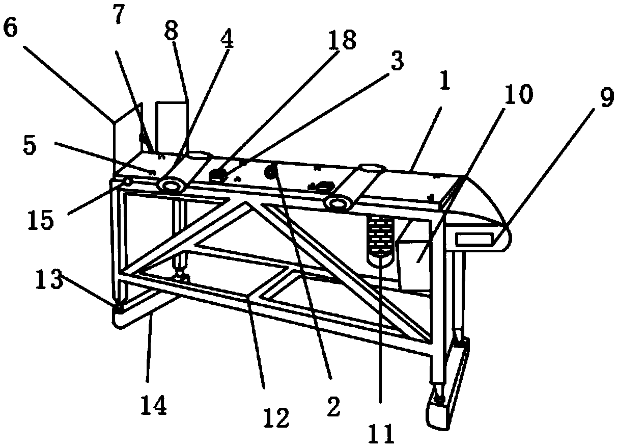
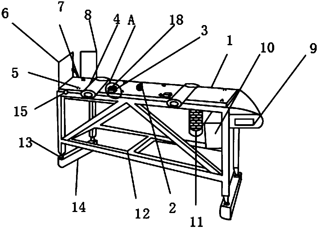
[0018] Such as Figure 1-4 As shown, a polishing machine discharge frame with a baffle includes a discharge frame main body 1, an optical sensor 7 and a fixed frame 12, the upper end of the discharge frame main body 1 is provided with a material transfer cylinder 2, and the material transfer Both sides of the cylinder 2 are provided with a material jacking mechanism 3, one side of the material jacking mechanism 3 is provided with a roller 4, and one side of the roller 4 is provided with a resistance wheel 5, one part of the discharge frame main body 1 The side is provided with a baffle plate 6, and the main body 1 of the discharge rack is movably connected with the baffle plate 6 through a light sensor 7. One side of the light sensor 7 is provided...


PUM


Abstract

The invention discloses a polisher discharge rack with a baffle plate. The rack comprises a discharge rack main body, a light sensor and a fixing frame, one side of the discharge rack main body is provided with the baffle plate, one side of the light sensor is provided with a falling proof plate, the other side of the discharge rack main body is provided with a counter, the inside of an operationbox is provided with a circuit breaker, the outer surface of the operation box is provided with a control panel, one side of the operation box is provided with a driving motor, the lower end of a fixing frame is provided with a hydraulic column, an anti-vibration base and the discharge frame main body are fixedly connected, and the outer surface of the discharge rack main body is provided with anemergency stop button. The polisher discharge rack with the baffle plate is provided with a rubber cushion layer, the baffle plate and the hydraulic column, can prevent damages caused by a top material mechanism directly contacting materials, and can prevent wear on the surface caused by discharging products falling down, the height of the discharge rack can be effectively adjusted, and the polisher discharge rack is suitable for different working conditions, and brings better use prospects.

Description

technical field [0001] The invention relates to the field of mechanical equipment, in particular to a discharge frame of a polishing machine with a baffle. Background technique [0002] A polishing machine is a mechanical device that grinds the outer surface of an object. The key to the operation of the polishing machine is to try to obtain the maximum polishing rate so as to remove the damaged layer produced during polishing as soon as possible. At the same time, it is necessary to ensure that the polishing damage layer will not affect the final observed tissue, that is, it will not cause false tissue. The former requires the use of coarser abrasives to ensure a greater polishing rate to remove the polished damage layer, but the polishing damage layer is also deeper, while the latter requires the use of the finest materials to make the polishing damage layer shallower, but the polishing damage layer is also deeper. The rate is low. In the process of polishing, a discharge...

Claims


Application Information

Patent Timeline
IPC IPC(8): B24B41/02
CPCB24B41/02
Inventor 单伟民
Owner 单伟民
Why Eureka
Try Eureka