
Equipment for cement laying on inclined wall of ditch

A cement and ditch technology, applied in cement mixing devices, water conservancy projects, artificial waterways, etc., can solve the problem of cement easily slipping to the bottom of the ditch, etc., and achieve the effect of preventing cement precipitation and cement leveling.

Active Publication Date: 2018-11-23
NANTONG TAIYING NEW MATERIAL SCI & TECH CO LTD
View PDF6 Cites 0 Cited by
  • Summary
  • Abstract
  • Description
  • Claims
  • Application Information

AI Technical Summary

Problems solved by technology

[0004] In order to overcome the disadvantage of the cement in the prior art that the cement is easy to slip to the bottom of the ditch when laying cement on the inclined wall of the ditch, the technical problem of the present invention is to provide a cement laying equipment for the inclined wall of the ditch that can prevent the cement from slipping when the inclined wall is laid.

Method used


Image

  • Equipment for cement laying on inclined wall of ditch
  • Equipment for cement laying on inclined wall of ditch
  • Equipment for cement laying on inclined wall of ditch

Examples


Embodiment 1

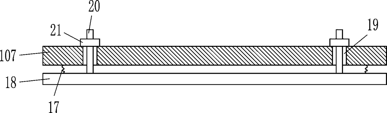
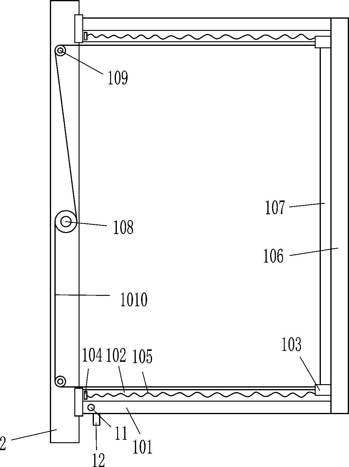
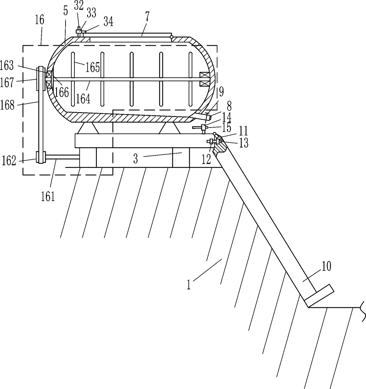
[0026] A kind of trench wall cement laying equipment, such as Figure 1-7As shown, it includes mounting plate 2, wheels 3, feet 4, cement box 5, cover plate 7, discharge pipe 8, large valve 9, cement paving device 10, first nut 12, first bolt 13, second Nut 14 and the second bolt 15, the top right of ditch body 1 is provided with mounting plate 2, the bottom of mounting plate 2 is equipped with wheels 3 on the front, rear, left, and right sides, and the upper side of mounting plate 2 is connected with feet 4, feet 4 The upper side is provided with a cement box 5, and the middle part of the upper side of the cement box 5 is provided with a feeding hole 6. The cement box 5 on the right side of the feeding hole 6 is hingedly connected with a cover plate 7, and the lower right side of the cement box 5 is embedded with a Discharge pipe 8, a large valve 9 is installed in the discharge pipe 8, the right end of the mounting plate 2 is hingedly connected with a cement paving device 10,...

Embodiment 2

[0028] A kind of trench wall cement laying equipment, such as Figure 1-7 As shown, it includes mounting plate 2, wheels 3, feet 4, cement box 5, cover plate 7, discharge pipe 8, large valve 9, cement paving device 10, first nut 12, first bolt 13, second Nut 14 and the second bolt 15, the top right of ditch body 1 is provided with mounting plate 2, the bottom of mounting plate 2 is equipped with wheels 3 on the front, rear, left, and right sides, and the upper side of mounting plate 2 is connected with feet 4, feet 4 The upper side is provided with a cement box 5, and the middle part of the upper side of the cement box 5 is provided with a feeding hole 6. The cement box 5 on the right side of the feeding hole 6 is hingedly connected with a cover plate 7, and the lower right side of the cement box 5 is embedded with a Discharge pipe 8, a large valve 9 is installed in the discharge pipe 8, the right end of the mounting plate 2 is hingedly connected with a cement paving device 10...

Embodiment 3

[0031] A kind of trench wall cement laying equipment, such as Figure 1-7 As shown, it includes mounting plate 2, wheels 3, feet 4, cement box 5, cover plate 7, discharge pipe 8, large valve 9, cement paving device 10, first nut 12, first bolt 13, second Nut 14 and the second bolt 15, the top right of ditch body 1 is provided with mounting plate 2, the bottom of mounting plate 2 is equipped with wheels 3 on the front, rear, left, and right sides, and the upper side of mounting plate 2 is connected with feet 4, feet 4 The upper side is provided with a cement box 5, and the middle part of the upper side of the cement box 5 is provided with a feeding hole 6. The cement box 5 on the right side of the feeding hole 6 is hingedly connected with a cover plate 7, and the lower right side of the cement box 5 is embedded with a Discharge pipe 8, a large valve 9 is installed in the discharge pipe 8, the right end of the mounting plate 2 is hingedly connected with a cement paving device 10...


PUM


Abstract

The invention relates to cement laying equipment, in particular to equipment for cement laying on an inclined wall of a ditch. In order to solve technical problems in the prior art, the equipment which is used for cement laying on the inclined wall of the ditch and is capable of preventing cement from slipping when the cement is laid on the inclined wall is provided. According to the technical implementation scheme, the equipment for cement laying on the inclined wall of the ditch comprises a mounting plate, wheels, cushion blocks, a cement tank, a cover plate, a discharging pipe, a large valve, a cement laying device, a first nut, a first bolt, a second nut and a second bolt, wherein the mounting plate is arranged on the upper right of a ditch body; the wheels are mounted on the front, rear, left and right sides of the bottom of the mounting plate; the cushion blocks are connected with the front, rear, left and right sides of the upper side of the mounting plate; and the cement tank is arranged on the upper sides of the cushion blocks. According to the equipment provided by the invention, cement in the cement tank is stirred through a stirring device and protected against precipitation; through the cement laying device, the cement is laid on the inclined wall of the ditch; and accordingly, the equipment achieves the effects that the cement can be prevented from slipping when being laid on the inclined wall, and meanwhile, the laid cement can become smoother.

Description

technical field [0001] The invention relates to cement laying equipment, in particular to cement laying equipment for inclined walls of ditches. Background technique [0002] The ditch is an important water conservancy project. In order to prevent the water in the ditch from seeping into the ground, it is necessary to lay cement on the outer wall of the ditch, but the outer wall of the ditch is usually inclined, so when laying cement on the inclined wall, the cement is easy to fall from the inclined wall. The wall slides down to the bottom of the ditch, which will not only waste cement, but also cause the bottom of the ditch to become higher, affecting the water flow in the ditch. [0003] To sum up, it is necessary to develop a ditch inclined wall cement laying equipment that can prevent the cement from slipping when laying cement on the inclined wall, so as to overcome the shortcomings of the prior art that the cement is easy to slip to the bottom of the ditch when laying ...

Claims


Application Information

Patent Timeline
Patent Type & Authority Applications(China)
IPC IPC(8): B28C5/14B28C5/08E02B5/02E02D15/02
CPCB28C5/0812B28C5/0831B28C5/0856B28C5/0893B28C5/148E02B5/02E02D15/02
Inventor 刘平
Owner NANTONG TAIYING NEW MATERIAL SCI & TECH CO LTD
Features
  • Generate Ideas
  • Intellectual Property
  • Life Sciences
  • Materials
  • Tech Scout
  • Unparalleled Data Quality
  • Higher Quality Content
  • 60% Fewer Hallucinations
Learn More