Concrete mixing equipment with dredging and cleaning functions

A technology for mixing equipment and concrete, which is applied to mixer accessories, clay preparation devices, cement mixing devices, etc., can solve the problems of unsmooth discharge of the discharge pipe, affect the discharge speed, and reduce the practicability, and achieve a flexible structure of the dredging mechanism. , Prevent cement accumulation and ensure the effect of discharging

Inactive Publication Date: 2018-11-23
HENAN VOCATIONAL COLLEGE OF APPLIED TECH +1
View PDF8 Cites 16 Cited by
  • Summary
  • Abstract
  • Description
  • Claims
  • Application Information

AI Technical Summary

Problems solved by technology

[0003] However, after the existing concrete runs, part of the cement will adhere to the inner wall of the mixing drum and the discharge pipe. As the number of operations increases, the cement accumulated on the inner wall of the mixing drum and the discharge pipe will gradually increase, resulting in the discharge pipe The discharge is not smooth, which affects the discharge speed, and in severe cases, it will cause blockage. Not only that, the cement solidified on the inner wall of the mixing drum will also block the rotation of the blades inside the mixing drum and affect the mixing, which will lead to the existing concrete mixing. Reduced availability of equipment

Method used


Image

  • Concrete mixing equipment with dredging and cleaning functions
  • Concrete mixing equipment with dredging and cleaning functions
  • Concrete mixing equipment with dredging and cleaning functions

Examples


Embodiment Construction

[0027] The present invention is described in further detail now in conjunction with accompanying drawing. These drawings are all simplified schematic diagrams, which only illustrate the basic structure of the present invention in a schematic manner, so they only show the configurations related to the present invention.

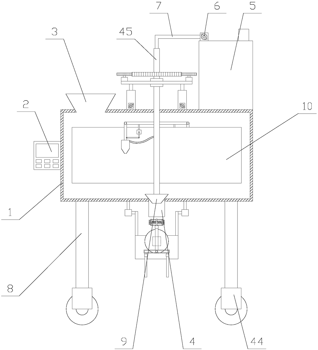
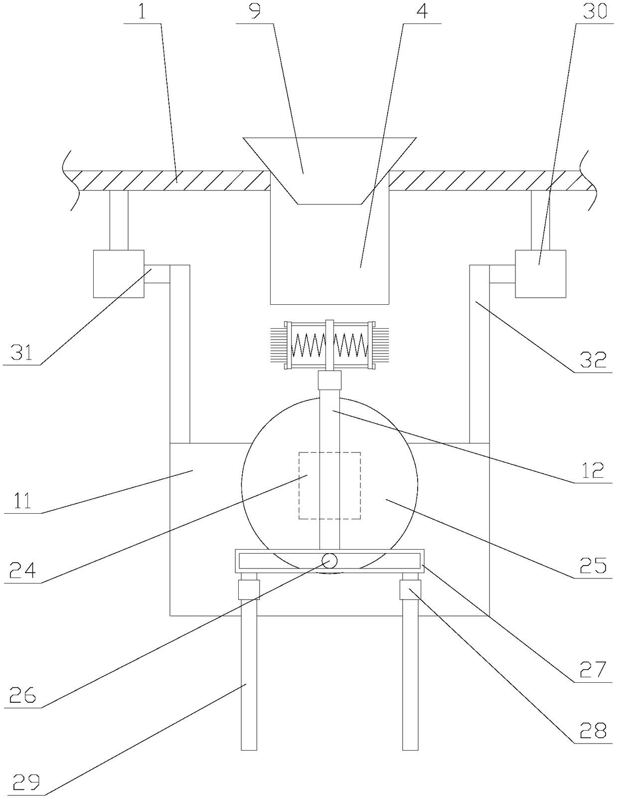
[0028] Such as figure 1 As shown, a concrete mixing equipment with dredging and cleaning functions, including a mixing drum 1, a controller 2, a feeding pipe 3, a discharging pipe 4, a water tank 5, a water pump 6, a suction pipe 7, a rotating pipe 45, and a driving mechanism , a dredging mechanism, a rotating tube 45 and some legs 8, the legs 8 are fixed below the mixing drum 1, the controller 2 is fixed on one side of the mixing drum 1, the controller 2 is provided with a PLC, the The water tank 5 and the feed pipe 3 are all fixed on the top of the mixing drum 1, the water pump 6 is fixed on the top of the water tank 5, the water tank 5 is provided with a w...


PUM


Abstract

The invention relates to concrete mixing equipment with dredging and cleaning functions. The concrete mixing equipment comprises a mixing barrel, a feeding pipe, a discharging pipe, a water tank, a water pump, a water suction pipe, a rotation pipe, a drive mechanism, a dredging mechanism and a rotation pipe. A stop block, two mixing plates and two cleaning mechanisms are arranged in the mixing barrel. The dredging mechanism comprises a flat plate, a reciprocating assembly, a connecting plate, a dredging assembly and two rotation assemblies. The dredging assembly comprises a first motor, a first drive shaft and two dredging units. Each cleaning mechanism comprises a side rod, a swinging rod, a sprayer, a water conveying pipe and a direction adjusting assembly. According to the concrete mixing equipment with the dredging and cleaning functions, the cleaning mechanisms are used for scouring and cleaning the interior of the mixing barrel after mixing is finished, and cement stacking is prevented; in addition, through the dredging mechanism, a brush rotates on the inner wall of the discharging pipe and moves up and down, attached cement is scraped away, and discharging pipe cleaning anddredging are achieved; and discharging blockage caused by cement stacking is avoided, and the practicability of the equipment is improved.

Description

technical field [0001] The invention relates to the field of construction equipment, in particular to a concrete mixing equipment with dredging and cleaning functions. Background technique [0002] Concrete mixer is a machine that mixes cement, sand aggregate and water to make concrete mixture. It is mainly composed of mixing drum, feeding and unloading mechanism, water supply system, prime mover, transmission mechanism, frame and supporting device. Mixers are commonly used on various construction sites. [0003] However, after the existing concrete runs, part of the cement will adhere to the inner wall of the mixing drum and the discharge pipe. As the number of operations increases, the cement accumulated on the inner wall of the mixing drum and the discharge pipe will gradually increase, resulting in the discharge pipe The discharge is not smooth, which affects the discharge speed, and in severe cases, it will cause blockage. Not only that, the cement solidified on the in...

Claims


Application Information

Patent Timeline
Patent Type & Authority Applications(China)
IPC IPC(8): B28C5/16B28C5/08B28C7/12B01F15/00
CPCB28C5/0806B28C5/0818B28C5/0831B28C5/0893B28C5/16B28C7/126B01F35/121B01F35/1453
Inventor 陈科
Owner HENAN VOCATIONAL COLLEGE OF APPLIED TECH
Why Eureka
Try Eureka