Air conditioning structure for rail traffic and rail traffic

A rail transit and air conditioning technology, applied in the field of rail transit, can solve the problems of inability to guarantee the heat exchange effect, unsatisfactory heat exchange effect, limited head space, etc., and achieve the effects of smooth air outlet, space saving, and small air supply resistance.

Pending Publication Date: 2018-11-23
SICHUAN ZHONGTANG SKY RAILWAY TECH CO LTD
View PDF0 Cites 2 Cited by
  • Summary
  • Abstract
  • Description
  • Claims
  • Application Information

AI Technical Summary

Problems solved by technology

[0003] In the above settings, due to the limited space at the top of the rail transit carriage (1), the air duct can only be arranged in a narrow space, which cannot guarantee the heat exchange effect; at the same time, due to the large air supply resistance, the heat exchange effect is not ideal

Method used


Image

  • Air conditioning structure for rail traffic and rail traffic
  • Air conditioning structure for rail traffic and rail traffic
  • Air conditioning structure for rail traffic and rail traffic

Examples


Embodiment 1

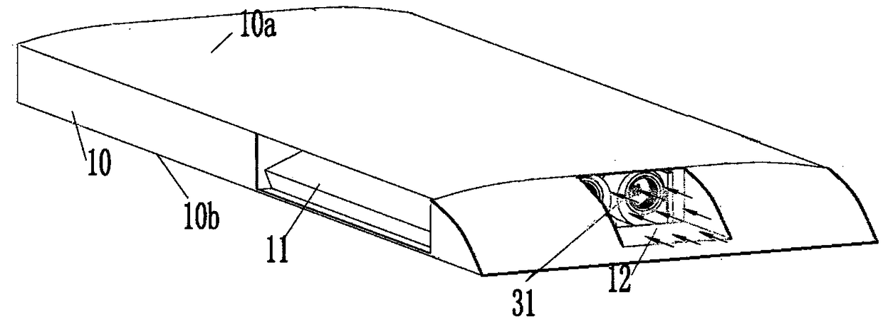
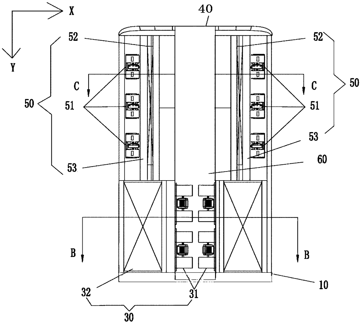
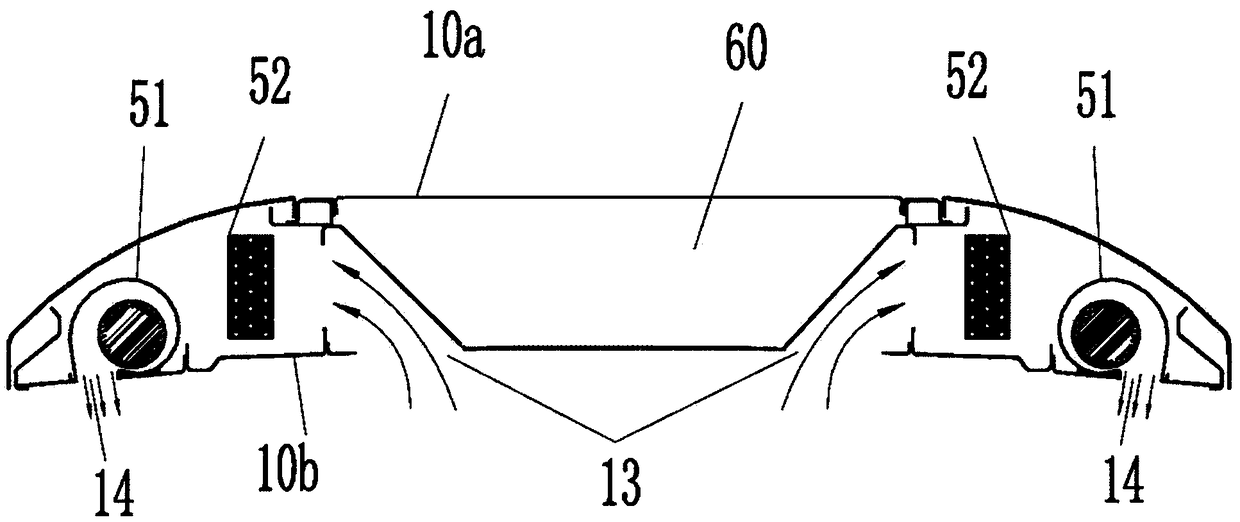
[0036] Such as Figure 1-5 As shown, the application provides a rail transit air-conditioning structure, including: an air-conditioning body 10 and a first heat exchanger assembly 30 and a second heat exchanger assembly 50 disposed in the air-conditioning body 10; the air-conditioning body 10 Including a fairing 10a and a bottom plate 10b; the front end of the fairing 10a is provided with an air inlet 12, the rear end of the fairing 10a is provided with a vent 40, and the side of the fairing 10a is provided with a first air outlet 11, the The bottom plate 10b is provided with an air return port 13 and a second air outlet 14; in the longitudinal direction of the rail transit car 1, the second heat exchanger assembly 50 and the first heat exchanger assembly 30 are arranged front and back; A heat exchanger assembly 30 includes a first heat exchange air passage, and the air inlet 12 communicates with the first air outlet 11 through the first heat exchange air passage; the second h...

Embodiment 2

[0040] Such as Figure 1-5 As shown, the difference between this embodiment and embodiment 1 only lies in:

[0041] The outer surface of the fairing 10a is streamlined. Several triangular reinforcing plates are arranged between the fairing 10a and the bottom plate 10b. The second air outlet 14 communicates with the indoor air.

[0042]The first heat exchanger assembly 30 is a condenser assembly, the first heat exchanger 32 is a condenser, and the first heat exchange air channel is a condensation air channel; the second heat exchanger assembly 50 is an evaporator assembly, and the second heat exchanger 52 is an evaporator, and the second heat exchange air duct 53 is an evaporation air duct. The first heat exchanger assembly 30 includes two first heat exchange air passages, the first heat exchange air passages are provided with a first fan 31 and a first heat exchanger 32, and the first fan 31 Relative to the first heat exchanger 32 , it is arranged closer to the air inlet 4...

Embodiment 3

[0045] Such as Figure 1-5 As shown, the difference between this embodiment and Embodiment 2 is only that: the first heat exchanger assembly 30 is an evaporator assembly, the first heat exchanger 32 is an evaporator, and the first heat exchange air duct is an evaporation air duct; The heat exchanger assembly 50 is a condenser assembly, the second heat exchanger 52 is a condenser, and the second heat exchange air channel 53 is a condensation air channel.


PUM


Abstract

The invention discloses an air conditioning structure for rail traffic and the rail traffic. The structure includes an air conditioner body, a first heat exchanger component and a second heat exchanger component, and the first heat exchanger component and the second heat exchanger component are arranged in the air conditioner body. The air conditioner body includes a fairing hood and a bottom plate; the front end of the fairing hood is provided with an air inlet, the rear end of the fairing hood is provided with an air vent, the side face of the fairing hood is provided with a first air outlet, and the bottom plate is provided with a return air inlet and a second air outlet. The first heat exchanger component includes a first heat exchange air duct, the air inlet is communicated with the first air outlet through the first heat exchange air duct, the second heat exchanger component includes second heat exchange air ducts, and the second heat exchange air ducts are communicated with thereturn air outlet and the second air outlet in sequence; the second heat exchange air ducts and the first heat exchange air duct are separated, and a decompression passage is arranged in the air conditioner body and communicated with the first heat exchange air duct and the air vent; in the horizontal direction of a carriage, the second heat exchange air ducts are arranged on the left side and right side of the decompression passage. The air conditioning structure for the rail traffic saves space, air supply resistance can be reduced, and the heat exchange effect is improved.

Description

technical field [0001] The invention relates to the field of rail transportation, in particular to a rail transportation air-conditioning structure and the rail transportation. Background technique [0002] In the prior art, rail transit air conditioners generally have a two-stage layout, including heat exchange components (including evaporator components and condenser components) and electrical appliances and compressors (70) along the longitudinal direction of the vehicle (from front to rear). Mainly comprise compressor (70) storehouse and electric appliance storehouse). Wherein, the evaporator assembly mainly includes an evaporating fan, an evaporator, and an air return port, and the condenser assembly includes a condensing fan, a condenser, and a first air inlet. [0003] In the above setting, due to the limited space at the top of the rail transit carriage (1), the air duct can only be arranged in a narrow space, which cannot guarantee the heat exchange effect; meanwhi...

Claims


Application Information

Patent Timeline
Patent Type & Authority Applications(China)
IPC IPC(8): B61D27/00
CPCB61D27/00
Inventor 谢君曾正元许俊宋丹明叶晓龙官海君吴剑峰唐通
Owner SICHUAN ZHONGTANG SKY RAILWAY TECH CO LTD
Why Eureka
Try Eureka