

Double-hopper charging device with double-side sealed hoisting sleeve and working method thereof
A technology of lifting sleeves and double hoppers, which is applied in the petroleum industry, coke cooling, coke ovens, etc., can solve the problems of high work intensity, increased equipment costs and operating costs, and large randomness of cloth distribution, so as to reduce equipment costs and The effect of reducing operating costs, preventing dust from escaping, and reducing material segregation
- Summary
- Abstract
- Description
- Claims
- Application Information
AI Technical Summary
Problems solved by technology
Method used
Image

Examples
Embodiment Construction
[0051] The specific embodiment of the present invention will be further described below in conjunction with accompanying drawing:
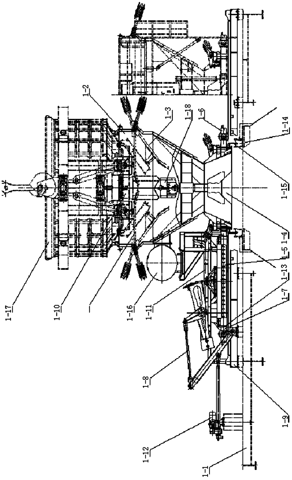
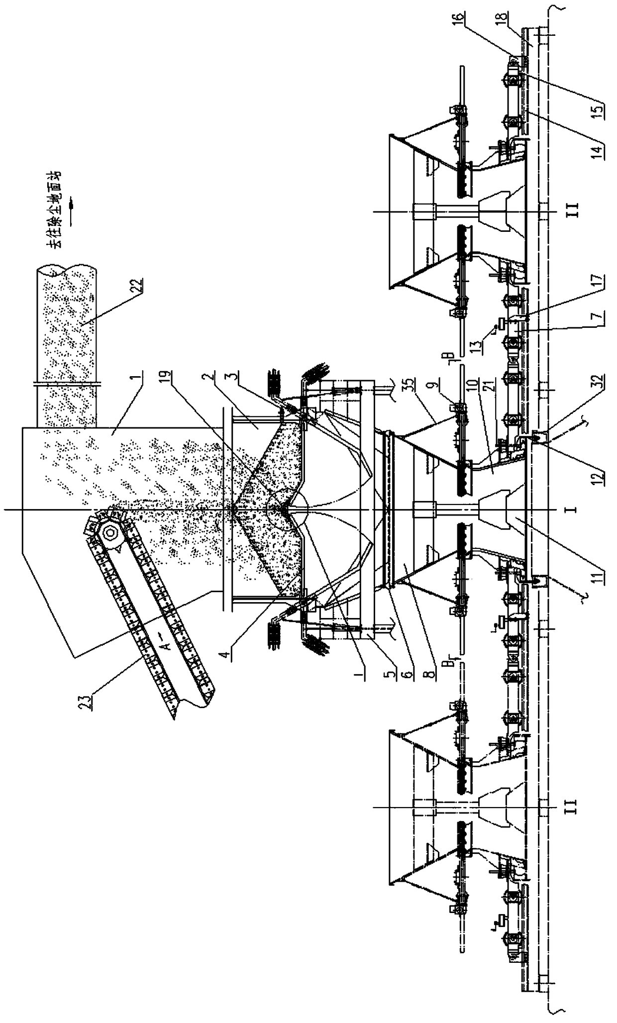
[0052] Such as figure 1 As shown, a double hopper loading device with double-sided sealing of the lifting sleeve according to the present invention includes an upper hopper 5, a lower hopper 12, a hopper support 6, a trolley 4, a water seal cover 14 and a dust collection pipe 23; It includes a discharge pipe 8, a lifting sleeve 9, an upper sealing mechanism 10, a lower sealing mechanism 41 and a guiding mechanism 11; a track 17 is provided on the loading platform 22 at the top of the CDQ furnace, and two interconnected For trolleys 4, one of the trolleys is located at the charging position I above the furnace mouth, and the other trolley 4 is located at the inspection position II on one side; the configurations on the two trolleys 4 are the same, as two independent There are two loading units, one for work and one for preparation; in each loading...
PUM
 Abstract
Description
Claims
Application Information