Cooling device for high-temperature powdery material and using method thereof

A powdery material and cooling device technology, applied in fixed tubular conduit components, heat exchange equipment, direct contact heat exchangers, etc., can solve cooling operations with high infrastructure and operating costs, large cooling gas consumption, secondary mine Phase transition and other issues, to achieve the effect of low operating cost and equipment cost, guaranteed cooling effect, and less moving parts

Pending Publication Date: 2020-08-18
CHANGSHA RES INST OF MINING & METALLURGY
View PDF0 Cites 0 Cited by
  • Summary
  • Abstract
  • Description
  • Claims
  • Application Information

AI Technical Summary

Problems solved by technology

However, the specific heat capacity of gas is generally small, and a large amount of cooling air must be consumed in order to cool high-temperature materials. On the one hand, due to the large cooling area, the cooling operation infrastructure and operating costs are high; on the other hand, the dust-laden flue gas after heat exchange It must be dust-removed bef

Method used


Image

  • Cooling device for high-temperature powdery material and using method thereof
  • Cooling device for high-temperature powdery material and using method thereof
  • Cooling device for high-temperature powdery material and using method thereof

Examples


Example Embodiment

[0034] Example 1:

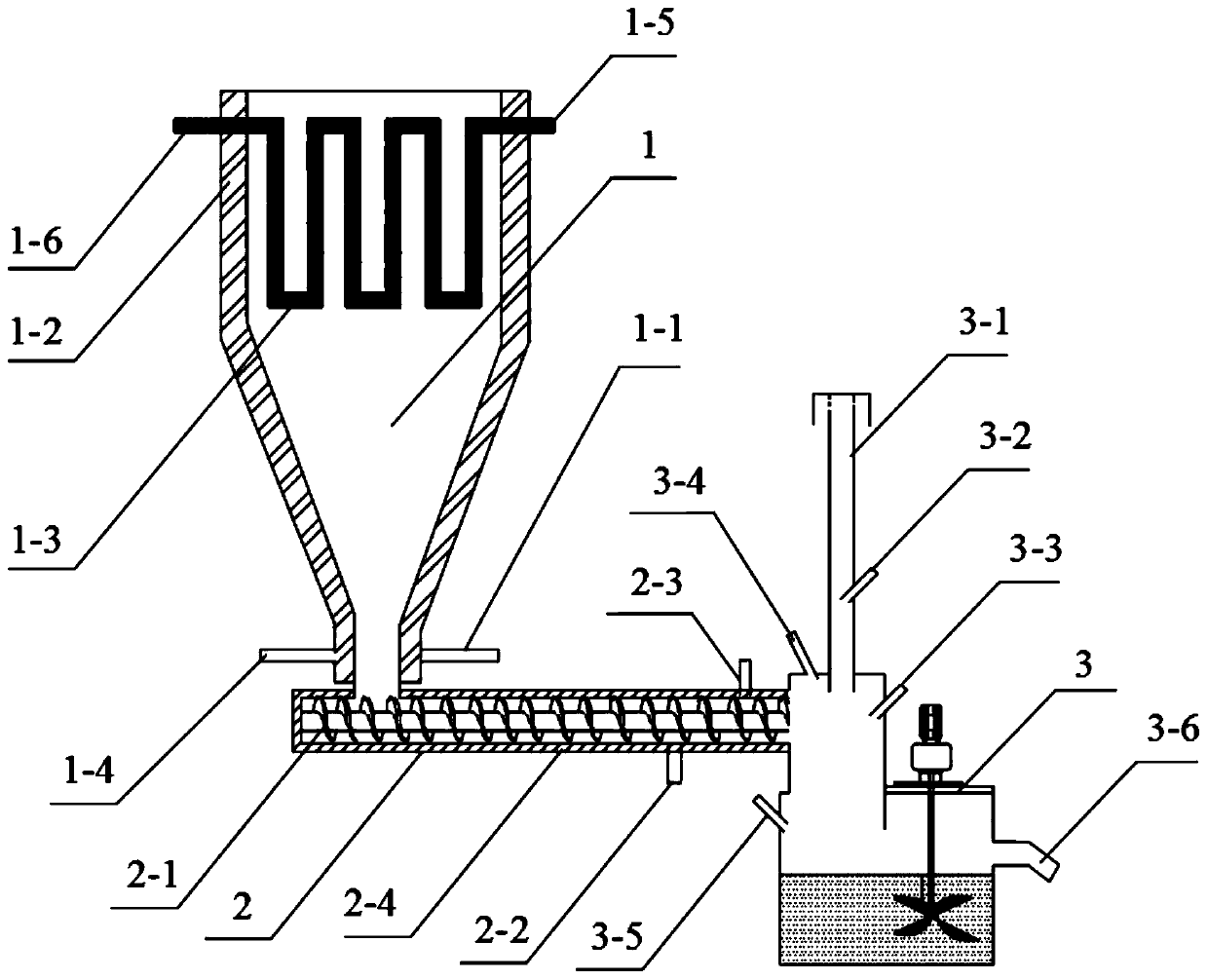
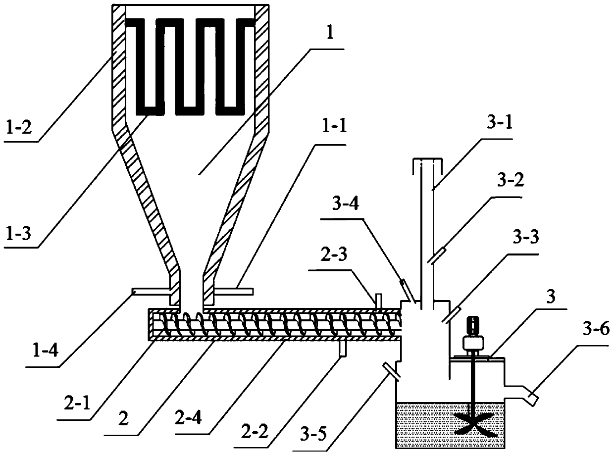
[0035] A cooling device for high-temperature powdery materials, such as figure 1 As shown, it includes a cooling silo 1, a spiral cooler 2, a mixing barrel 3, and attached connecting pipes and valves. The cooling silo 1 of this embodiment is installed directly below the material flow outlet of the fine ore high temperature pretreatment device, and is connected to the fine ore high temperature pretreatment material flow outlet through a high temperature resistant pipeline, and the cooling silo 1 discharge port is through a high temperature resistant pipeline It is connected with the feed port of the screw cooler 2, the discharge port of the screw cooler 2 is connected with the feed port of the mixing tank 3, and the cooling slurry outlets 3-6 of the mixing tank 3 are connected to the subsequent processing procedures through pipelines.

[0036] The outer wall of the cooling silo 1 of this embodiment is provided with a silo cooling water jacket 1-2, and the silo co...

Example Embodiment

[0044] Example 2:

[0045] A cooling device for high-temperature powdery materials, such as figure 1 As shown, it includes a cooling silo 1, a spiral cooler 2, a mixing barrel 3, and attached connecting pipes and valves. The cooling silo 1 of this embodiment is installed directly below the material flow outlet of the fine ore high temperature pretreatment device, and is connected to the fine ore high temperature pretreatment material flow outlet through a high temperature resistant pipeline, and the cooling silo 1 discharge port is through a high temperature resistant pipeline It is connected with the feed port of the screw cooler 2, the discharge port of the screw cooler 2 is connected with the feed port of the mixing tank 3, and the cooling slurry outlets 3-6 of the mixing tank 3 are connected to the subsequent processing procedures through pipelines.

[0046] The outer wall of the cooling silo 1 of this embodiment is provided with a silo cooling water jacket 1-2, and the silo co...


PUM


Abstract

The invention discloses a cooling device for a high-temperature powdery material. The cooling device comprises a cooling bin, a spiral cooling machine and a stirring barrel, wherein a feeding openingof the spiral cooling machine is connected with a discharging opening of the cooling bin; a discharging opening of the spiral cooling machine is connected with a feeding opening of the stirring barrel; a bin cooling water jacket is arranged on the outer wall of the cooling bin, a spiral cooling water jacket is arranged on the outer wall of the spiral cooling machine, and a spiral reamer is arranged inside the spiral cooling machine. The cooling device can cool the high-temperature powdery material and recycle waste heat for effective utilization, combines liquid-solid direct heat exchange andindirect heat exchange mutually, is high in heat exchange efficiency, low in operation cost and device cost, stable in operation, capable of saving energy, environmentally friendly and high in adaptability, and has great significance in cooling of the high-temperature powdery material and waste heat utilization. The invention further discloses a using method of the cooling device. The using methodhas the advantages of being easy to operate, low in operation cost, easy to maintain, green and environmentally friendly.

Description

technical field [0001] The invention relates to the fields of ore dressing, metallurgy and environmental protection, in particular to a cooling device for high-temperature powdery materials and a method for using the device. Background technique [0002] my country's ferrous metal mineral resources such as iron ore and manganese ore are relatively poor in endowment, and have the characteristics of "poor", "fine", "miscellaneous" and "scattered". According to USGS statistics, the average grade of iron ore in the world is 48.82%, while the average grade of iron ore in China is only 34.29%, which is far lower than the world average; lean ore accounts for a large proportion, and more than 95% of iron ore resources need to be enriched through beneficiation. It can be economically and rationally developed and utilized, of which limonite, siderite and mixed iron ore account for about 18%. A large number of laboratory tests and production practices have shown that magnetization roast...

Claims


Application Information

Patent Timeline
IPC IPC(8): F28D7/08F28D11/00F28C3/12F28F5/04F28F5/06
CPCF28C3/12F28D7/082F28D11/00F28F5/04F28F5/06
Inventor 陈雯李家林刘小银陆晓苏彭泽友廖振鸿
Owner CHANGSHA RES INST OF MINING & METALLURGY
Why Eureka
Try Eureka