Connection joint between prefabricated reinforced concrete superposed beam and steel pipe column and construction method thereof
A reinforced concrete and connecting node technology, which is applied in the direction of architecture and building structure, can solve the problems of cumbersome node construction, inability to adapt to the development needs of prefabricated buildings, and large on-site workload, so as to achieve simple structure, convenient construction, and improved work efficiency. performance effect
- Summary
- Abstract
- Description
- Claims
- Application Information
AI Technical Summary
Problems solved by technology
Method used
Image

Examples
Embodiment 1
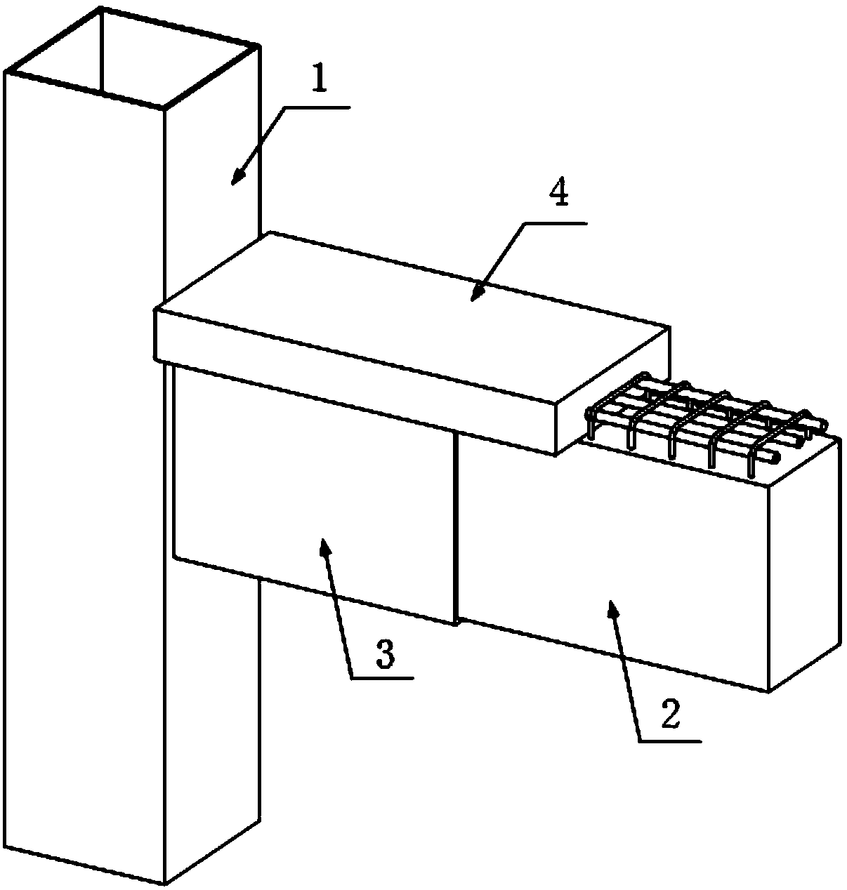
[0028] A connection node between a prefabricated reinforced concrete composite beam and a steel pipe column, characterized in that it mainly includes a prefabricated steel pipe column 1, a prefabricated reinforced concrete composite beam 2, a U-shaped steel sleeve 3 and cast-in-place concrete 4.
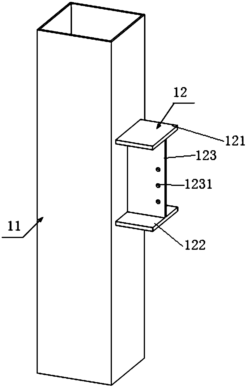
[0029] The prefabricated steel pipe column 1 includes a steel pipe column 11 and an H-shaped steel end 12 welded to the side wall of the steel pipe column 11 . The H-shaped steel end 12 includes an upper flange 121 , a lower flange 122 and a web 123 . There are several bolt holes I1231 on the web 123 . Both the upper flange plate 121 and the lower flange plate 122 of the H-shaped steel end 12 are parallel to the horizontal plane. The web 123 is perpendicular to the horizontal plane.
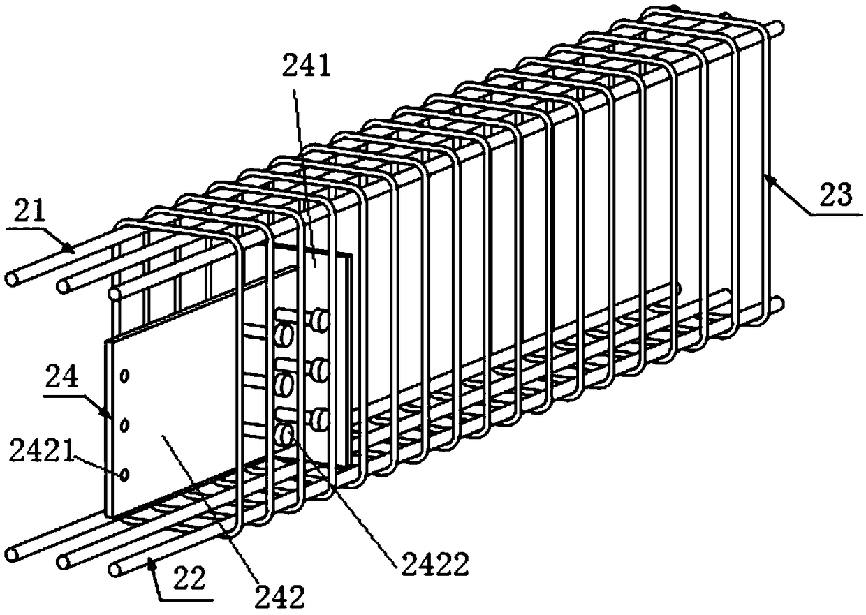
[0030] The prefabricated reinforced concrete composite beam 2 includes T-shaped connectors 24 and precast concrete 25 , as well as a reinforcement cage woven by several upper stressed steel bars 21 , ...
Embodiment 2
[0035] This embodiment discloses a construction method for the connection node between the reinforced concrete composite beam and the steel pipe column described in Embodiment 1, which is characterized in that the specific steps are as follows:
[0036] a. The prefabricated steel pipe column 1 and the prefabricated reinforced concrete composite beam 2 are processed in the factory, and after they are transported to the construction site and installed in place, they are connected with bolts 5.
[0037] b. Weld the upper stressed steel bar 21 and the lower stressed steel bar 22 of the prefabricated reinforced concrete composite beam 2 to the outer surfaces of the upper and lower flanges of the reserved H-shaped steel end 12 respectively.
[0038] c. Locate the everted U-shaped steel channel 31 and weld it to the outer wall of the steel pipe column 11 , and connect the steel bar 32 by welding.
[0039] d. Pouring concrete 4 to complete the construction.
[0040] Through the above...
PUM
 Abstract
Description
Claims
Application Information
 - R&D
- Intellectual Property
- Life Sciences
- Materials
- Tech Scout
- Unparalleled Data Quality
- Higher Quality Content
- 60% Fewer Hallucinations
Browse by: Latest US Patents, China's latest patents, Technical Efficacy Thesaurus, Application Domain, Technology Topic, Popular Technical Reports.
© 2025 PatSnap. All rights reserved.Legal|Privacy policy|Modern Slavery Act Transparency Statement|Sitemap|About US| Contact US: help@patsnap.com