Slot assembly type hollow glass brick and construction method thereof

A hollow glass and construction method technology, applied in building materials, building components, buildings, etc., can solve problems such as high requirements for construction technology, inability to lay circuit pipelines inside, and inconvenient construction of hollow glass brick walls, and achieve easy inspection and replacement , The effect of improving assembly accuracy

Pending Publication Date: 2018-11-23
邵一鸣
View PDF0 Cites 0 Cited by
  • Summary
  • Abstract
  • Description
  • Claims
  • Application Information

AI Technical Summary

Problems solved by technology

[0003] In order to overcome the problems that the existing hollow glass brick walls are inconvenient to construct, have high requirements for construction technology, and cannot lay circuit pipelines inside, the present invention provides a slot-assembled hollow glass brick and its construction method

Method used


Image

  • Slot assembly type hollow glass brick and construction method thereof
  • Slot assembly type hollow glass brick and construction method thereof
  • Slot assembly type hollow glass brick and construction method thereof

Examples


Embodiment Construction

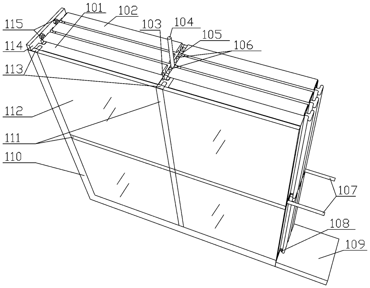
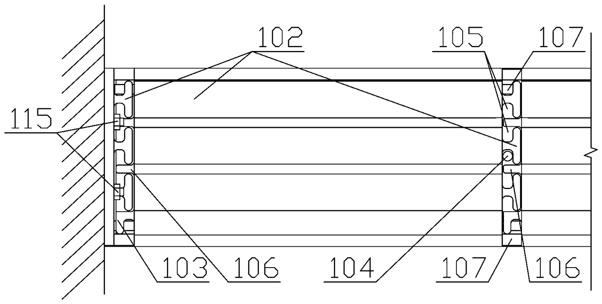
[0013] see figure 1 and figure 2 , the hollow glass block has slots on the four side walls of the upper, lower, left, and right sides. The upper, lower, and right sides are "T"-shaped slots (102), which engage with each other after plugged in (at the same time, the two ends and the middle three points are glued and fixed); the left side is "L"-shaped (103) and "I" "Type slot (106), the slot cavity (105) formed after being plugged and positioned with adjacent bricks or side slots, is used for laying reinforced steel bars or circuit pipelines. The bottom of the wall and the side frame of the wall also use positioning slots with "T"-shaped slots (102), and are fixed on the ground and side walls with the bottom positioning slot fixing bolts (108) and the side wall positioning slot fixing bolts (115) respectively. .

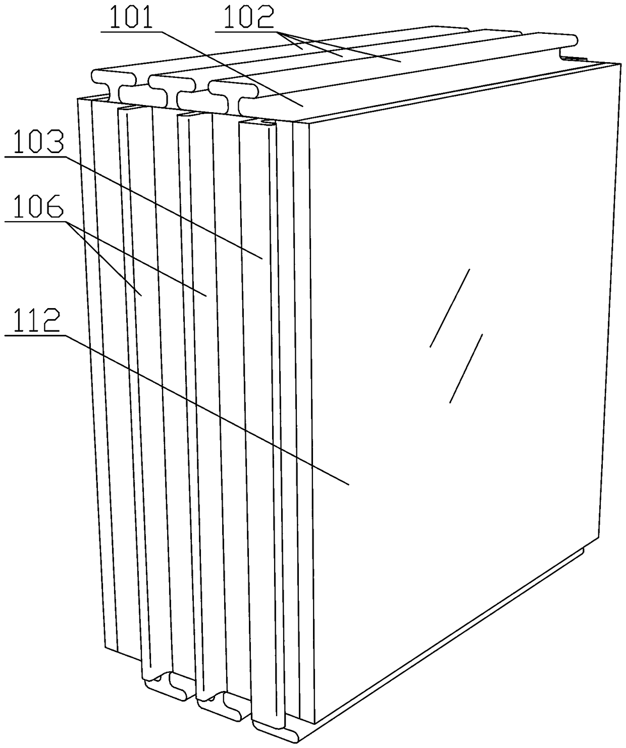
[0014] see image 3 , the slot cavity (105) formed after the "T"-shaped slot (102) on the right side of the left hollow glass block is plugged and positioned wit...


PUM


Abstract

The invention discloses a slot assembly type hollow glass brick and a construction method thereof. The hollow glass brick comprises a hollow glass brick body and positioning grooves, wherein side walls of the hollow glass brick body are provided with slots, and the positioning grooves are connected to and engage with the ground and the side walls. According to the hollow glass brick and the construction method thereof, the upper side wall, the lower side wall, the left side wall and the right side wall of the hollow glass brick body are provided with the slots, the slots on the upper side , the lower side and the right side are mutual-engaging type slots, are connected in an inserted mode and then engage with each other (meanwhile, an adhesive bonding and fixing mode is combined), the slots on the left side are non-mutual-engaging type positioning slots, are connected with adjacent bricks or edge grooves in an inserted mode and are positioned so as to form cavity parts, and the cavityparts are used for laying reinforcing steel bars or circuit pipelines; the interfaces between a hollow glass brick wall and the ground as well as the side walls are provided with the positioning grooves, the positioning grooves are provided with the slots which can engage with the slots of the side walls of the hollow glass brick body, and the wall bottom and wall side frames are fixed on the ground and the side walls through expansion bolts; and if the steel bars need to be laid, the ends of the steel bars penetrate through steel bar positioning holes in the wall bottom or the wall side positioning grooves and are buried in open holes of the ground or the side walls by more than 3 cm. The hollow glass brick and the construction method thereof have the advantages that the hollow glass brick body with the slots in the side walls and the positioning grooves in the ground surface and the side walls are utilized, by means of an inserted connection assembly mode, the construction method forthe hollow glass brick wall is simplified, and meanwhile, the function of laying the circuit pipelines in a wall body is additionally achieved.

Description

technical field [0001] The invention relates to a hollow glass brick and a construction method thereof, in particular to a slot-assembled hollow glass brick and a construction method thereof. Background technique [0002] At present, in the selection of interior decoration and even external maintenance walls (non-load-bearing walls), in addition to solid walls, glass brick walls (or partitions) are increasingly used, especially hollow glass brick walls. Its translucent characteristics ensure indoor lighting and proper privacy, and play a positive role in improving the aesthetics of the building's interior and exterior. At present, the common glass bricks usually need to be filled and connected with cement mortar (special adhesive is also used) during construction. The width of the joint needs to be controlled by plastic clamps. Experienced construction workers accurately lay out, measure, and control, and then wipe off excess mortar with a damp rag while pointing. At the s...

Claims


Application Information

Patent Timeline
IPC IPC(8): E04C1/42E04C1/39
CPCE04C1/397E04C1/42
Inventor 邵一鸣
Owner 邵一鸣
Why Eureka
Try Eureka