Insulating gas inflating method for electrical equipment

A technology for insulating gas and electrical equipment, which is applied in the field of insulating gas inflation, and can solve the problems of excessive inflation speed, violent collision of gas, and violent collision of insulating gas of power equipment.

Inactive Publication Date: 2018-11-23
ELECTRIC POWER RESEARCH INSTITUTE, CHINA SOUTHERN POWER GRID CO LTD +1
View PDF6 Cites 1 Cited by
  • Summary
  • Abstract
  • Description
  • Claims
  • Application Information

AI Technical Summary

Problems solved by technology

[0003] At present, when filling insulating gas into electrical equipment, whether it is a mixed insulating gas or a single-medium insulating gas, it is directly inflated to the electrical equipment, and the entire inflation process is continuous and at a relatively constant inflation speed. To inflate, so that in the later stage

Method used


Image

  • Insulating gas inflating method for electrical equipment

Examples


Embodiment Construction

[0045] The technical solutions in the embodiments of the present invention will be clearly and completely described below in conjunction with the accompanying drawings in the embodiments of the present invention. Obviously, the described embodiments are only a part of the embodiments of the present invention, rather than all the embodiments. Based on the embodiments of the present invention, all other embodiments obtained by those of ordinary skill in the art without creative work shall fall within the protection scope of the present invention.

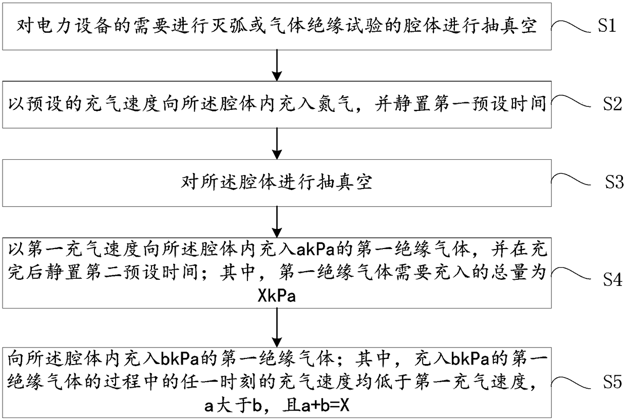
[0046] See figure 1 , The embodiment of the present invention provides an insulating gas charging method for power equipment, which includes the steps:

[0047] S1, vacuuming the cavity of the power equipment that needs arc extinguishing or gas insulation test (preferably, the absolute pressure is below 10 Pa).

[0048] S2: Fill the cavity with nitrogen at a preset charging speed, and stand still for a first preset time.

[0049] Exemplarily...


PUM


Abstract

The invention discloses an insulating gas inflating method for electrical equipment. The method comprises the steps that 1, a cavity to be subjected to arc extinguishing or gas insulating tests of theelectrical equipment is vacuumized; 2, nitrogen is inflated into the cavity at a preset inflating speed, and standing is carried out for a first preset time; 3, the cavity is vacuumized; and 4, a kPaof first insulating gas is inflated into the cavity at a first inflating speed, and standing is carried out for a second preset time after inflating is finished, wherein the inflating sum amount of the first insulating gas is X kPa; 5, b kPa of first insulating gas is inflated into the cavity, the inflating speed at any time in the process of inflating b kPa of first insulating gas is lower thanthe first inflating speed, a is larger than b, and the sum of a and b is equal to X. The whole inflating process of insulating gas is safe and smooth.

Description

Technical field [0001] The present invention relates to the technical field of power equipment, in particular to an insulating gas charging method for power equipment. Background technique [0002] SF 6 (Sulfur hexafluoride) gas, as an insulating gas for power equipment, has excellent insulation and arc extinguishing performance, and has been widely used in power grid equipment. Traditional SF 6 Due to the high greenhouse effect and the toxic decomposition products of the gas, its use must be basically restricted in 2020 according to the requirements of climate change related agreements. Therefore, in recent years, relevant domestic and foreign institutions have imposed restrictions on SF 6 Intensive research has been carried out on alternative gases. SF 6 Alternative gas includes two types: partial replacement and complete replacement. Among them, partial replacement means the use of SF 6 Mixture of other gases, for example, SF 6 Gas mixed with nitrogen, or CF 3 I gas is mixed ...

Claims


Application Information

Patent Timeline
IPC IPC(8): F17C5/06
CPCF17C5/06F17C2221/016
Inventor 罗颜傅明利卓然王邸博景一侯帅惠宝军张逸凡黄之明
Owner ELECTRIC POWER RESEARCH INSTITUTE, CHINA SOUTHERN POWER GRID CO LTD
Why Eureka
Try Eureka