An Optical Current Transformer Based on Strip Radial Polarization Grating

A technology of current transformer and polarization grating, applied in the direction of measuring only current, measuring current/voltage, instruments, etc., can solve the problems of affecting the outgoing light intensity, small dynamic measurement range, measurement error, etc., and achieve accurate measurement results and measurement range. big effect

Active Publication Date: 2020-11-10
FUZHOU UNIV
View PDF7 Cites 0 Cited by
  • Summary
  • Abstract
  • Description
  • Claims
  • Application Information

AI Technical Summary

Problems solved by technology

(2) Nonlinear measurement
The Faraday magneto-optical rotation angle needs to be controlled within a small angle (less than 1 degree) to achieve approximate linearity, resulting in a small dynamic measurement range
(3) Temperature drift problem
The temperature drift of light sources, optical devices, photoelectric conversion devices and electronic devices directly affects the intensity of the outgoing light, resulting in measurement errors

Method used


Image

  • An Optical Current Transformer Based on Strip Radial Polarization Grating
  • An Optical Current Transformer Based on Strip Radial Polarization Grating

Examples


Embodiment Construction

[0020] The present invention will be further described below in conjunction with the accompanying drawings and embodiments.

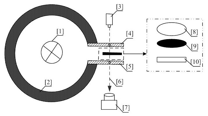
[0021] Please refer to figure 1 , the present invention provides an optical current transformer based on a strip-shaped radial polarization grating, which is characterized in that it includes a magnetic collecting ring 2, a light source 3, a first magnetic conductive plate 4, a second magnetic conductive plate 5, an optical path 6, CCD image sensor 7, polarizer 8, magneto-optical film 9 and shape radial polarization grating 10; Described magnetism collecting ring 2 is arranged on bus bar 1 outside; Described magnetism collecting ring 2 is provided with an opening, and described opening is arranged in parallel The first magnetically conductive plate 4 and the second magnetically conductive plate 5; the upper side of the first magnetically conductive plate 4 is provided with a light source 3; the lower side of the second magnetically conductive plate 5 is...


PUM


Abstract

The invention relates to an optical current transformer implemented through a bar-shaped radial polarization grating, and the current transformer comprises a magnetic collection ring, a light source,a first magnetic conductive plate, a second magnetic conductive plate, a CCD image sensor, a polarizer, a magneto-optic thin film, and the bar-shaped radial polarization grating. The magnetic collection ring is disposed outside a bus. The magnetic collection ring is provided with an opening, and the opening is provided with the first and second magnetic conductive plates in a parallel manner. Theupper side of the first magnetic conductive plate is provided with the light source. The lower side of the second magnetic conductive plate is provided with a CCD image sensor. The polarizer, the magneto-optic thin film, and the bar-shaped radial polarization grating are sequentially disposed between the first and second magnetic conductive plates from the top to the bottom. The first and second magnetic conductive plates are provided with through holes for the passing of an optical path. The optical current transformer enables the detection to be independent of optical power, achieves the linear measurement, and is large in measurement range.

Description

technical field [0001] The invention belongs to the technical field of electric power system current measurement, and in particular relates to an optical current transformer realized based on a bar-shaped radial polarization grating. Background technique [0002] Optical current transformer adopts optical sensing technology, which has the advantages of good insulation performance, strong anti-interference ability, no transient magnetic saturation, digitalization, etc., and meets the development needs of smart grid. The basic principle of optical current transformer is based on the Faraday magneto-optic effect, that is, when linearly polarized light passes through the magneto-optic material under the action of an external magnetic field parallel to its propagation direction, its polarization plane will rotate, and the rotation angle is proportional to the magnitude of the current . The existing detection mode cannot directly and linearly measure the rotation angle, but uses ...

Claims


Application Information

Patent Timeline
Patent Type & Authority Patents(China)
IPC IPC(8): G01R19/00
CPCG01R19/0092
Inventor 徐启峰黄奕钒谢楠
Owner FUZHOU UNIV
Why Eureka
Try Eureka