
Design method of biplane magnetic resonance imaging system gradient coil

A magnetic resonance imaging and design method technology, applied in the direction of measuring magnetic variables, measuring devices, instruments, etc., can solve the problems of large inductance of gradient coil wires and difficult wiring of gradient coils

Inactive Publication Date: 2018-11-23
河北惠仁医疗设备科技有限公司
View PDF7 Cites 11 Cited by
  • Summary
  • Abstract
  • Description
  • Claims
  • Application Information

AI Technical Summary

Problems solved by technology

[0004] The purpose of the present invention is to provide a method for designing gradient coils of a dual-plane magnetic resonance imaging system to solve the problem of large inductance of gradient coil wires in open magnetic resonance equipment
The minimum spacing is a constraint condition of the gradient coil, thus solving the problem of difficult wiring of the gradient coil

Method used


Image

  • Design method of biplane magnetic resonance imaging system gradient coil
  • Design method of biplane magnetic resonance imaging system gradient coil
  • Design method of biplane magnetic resonance imaging system gradient coil

Examples


Embodiment Construction

[0017] Embodiments of the present invention will be further described below in conjunction with the accompanying drawings.

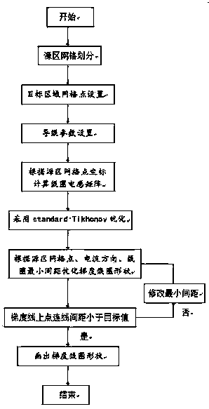
[0018] The following is a design embodiment of the gradient coil of a dual-plane magnetic resonance imaging system applying the present invention, and its design process is as follows figure 1 shown. The distance between the gradient coils is 0.54m, the diameter is 0.42m, the target gradient magnetic field of the designed gradient coil is 15mT / m, and the imaging area is a spherical area with a diameter of 0.4m.

[0019] In the first step, the gradient coil area of ​​the open magnetic resonance imaging system is divided into three-dimensional continuous triangular grids. In this embodiment, Maya2014 is used to divide the grids, and then the spherical surface in the imaging area is evenly divided into multiple target field points. Use MATLAB to divide a sphere with a diameter of 0.4m into 13 layers, with a test point every 30°, a total of 156 test points,...


PUM


Abstract

The present invention discloses a design method of a biplane magnetic resonance imaging system gradient coil. The method comprises the steps of: performing three-dimensional continuous triangular meshdivision for a gradient coil area, according to a boundary element method, calculating a coil inductance matrix generated by the gradient coil area mesh node for a target field point, calculating thecurrent and the direction of the gradient coil plane through a coil target gradient value, an inductance constraint condition and a Tikhonov Regularization, and finally employing a stream function method to obtain actual winding distribution of the gradient coil. The design method of a biplane magnetic resonance imaging system gradient coil solves the problem that the coil inductance is large inthe gradient coil.

Description

technical field [0001] The invention relates to a design method of a gradient coil of a double-plane magnetic resonance imaging system. Background technique [0002] The gradient coil is one of the original components of the magnetic resonance imaging equipment. Its main function is to add another gradient magnetic field that increases (or decreases) according to the location on the main magnetic field, so as to spatially locate and encode the MRI signal. In actual work, the gradient coil system must provide at least three kinds of gradient magnetic fields, namely layer selection, frequency encoding gradient and phase encoding gradient. The main indicators to measure the performance of gradient coils are imaging speed, resolution, noise level, etc. Improving the performance of gradient coils is of great significance to improving the performance of the entire nuclear magnetic resonance imaging system. [0003] At present, the BEM design of domestic gradient coils is mainly ...

Claims


Application Information

Patent Timeline
IPC IPC(8): G01R33/385
CPCG01R33/385
Inventor 李良安王天峰田焕霞
Owner 河北惠仁医疗设备科技有限公司
Learn More