Unlock instant, AI-driven research and patent intelligence for your innovation.

Laser ranging device

A technology of laser ranging and emitting device, applied in the field of laser ranging device and ranging device with green light indication, can solve the problem that the green light indication cannot correctly indicate the measurement target point, etc., and achieves accurate and intuitive indication and high sensitivity Effect

Pending Publication Date: 2018-11-23
JIANGSU LAITZ MEASURING& CONTROL TECH CO LTD +1
View PDF0 Cites 1 Cited by
  • Summary
  • Abstract
  • Description
  • Claims
  • Application Information

AI Technical Summary

Problems solved by technology

For machines with green light indicators in the prior art, the green light is generally parallel to but separated from the optical axis of the measurement signal transmission and reception. When measuring narrow targets, the green light indicator cannot correctly indicate the measurement target point

Method used


Image

  • Laser ranging device
  • Laser ranging device
  • Laser ranging device

Examples


Embodiment 1

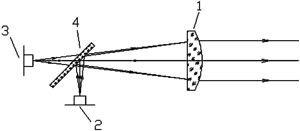
[0027] figure 1 It is a schematic diagram of the optical path in which the optical path of the green light indicating emitting device is coaxial with the optical path of the measuring signal emitting device. The measuring signal transmitting device and the green light indicating transmitting device share a collimating lens 1, and a first reflector 4 is arranged behind the collimating lens, the first reflecting mirror 4 forms a certain angle with the optical axis, and the measuring signal transmitting device 2 is positioned at the first On the reflection light path of the reflector 4, the green light indicator emitting device 3 is on the transmission light path of the first reflector 4, and the first reflector 4 reflects the measurement signal and transmits the indicator green light signal, so that the measurement signal and the indicator green light signal are coaxial .

[0028] figure 2 It is a structural schematic diagram of the coaxial structure of the optical path of th...

Embodiment 2

[0030] image 3 It is a schematic representation of the optical path in which the optical path of the green light indicates that the optical path of the emitting device is coaxial with the optical path of the measuring signal receiving device. The measuring signal receiving device and the green light indicator transmitting device share a receiving objective lens 7, and a second reflector 8 is arranged behind the receiving objective lens 7. The second reflector 8 forms a certain angle with the optical axis, and the measuring signal receiving device 9 is at the second reflection On the reflected light path of the mirror 8, the green light indicator emitting device 3 is on the transmitted light path of the second reflector 8, and the second reflector 8 reflects the measurement signal and transmits the indicator green light signal, so that the measurement signal reception and the indicator green light signal are coaxial .


PUM


Abstract

The invention discloses a laser ranging device. The laser ranging device comprises a measurement signal transmitting device used for transmitting measurement signals, a green light indication transmitting device used for transmitting indication green light, and a measurement signal receiving device used for receiving the measurement signals; the optical path of the green light indication transmitting device and the optical path of the measurement signal transmitting device share the same axis, or the optical path of the green light indication transmitting device and the optical path of the measurement signal receiving device share the same axis.

Description

technical field [0001] The invention relates to the technical field of laser ranging, and relates to a laser ranging device, in particular to a ranging device with a green light indicator. Background technique [0002] With the development of laser technology, laser ranging has been widely used in many industries, such as surveying and mapping, home improvement, construction, outdoor sports, etc. For the 100-meter laser distance measuring device, the red light source is generally used as the measurement signal. Although the measurement target can be well distinguished in the case of dark light, it is difficult for the human eye to distinguish in the case of strong ambient light. The red light measures the target point. [0003] The human eye is more sensitive to green light than red light, and is more sensitive to green light indication, thus ensuring safety. For machines with green light indicators in the prior art, the green light is generally parallel to but separated f...

Claims


Application Information

Patent Timeline
IPC IPC(8): G01S17/08G01S7/481
CPCG01S7/4812G01S17/08
Inventor 刘茜
Owner JIANGSU LAITZ MEASURING& CONTROL TECH CO LTD