
Optical film, backlight module and display device

An optical film and optical film technology, which is applied to identification devices, diffusing elements, instruments, etc., can solve the problems of difficult extraction and utilization of incident light at small angles, and achieve the effect of improving the utilization rate of light energy and improving the front brightness.

Active Publication Date: 2018-11-23
WUHAN CHINA STAR OPTOELECTRONICS TECH CO LTD
View PDF14 Cites 0 Cited by
  • Summary
  • Abstract
  • Description
  • Claims
  • Application Information

AI Technical Summary

Problems solved by technology

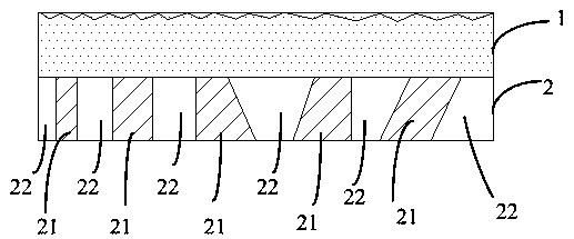
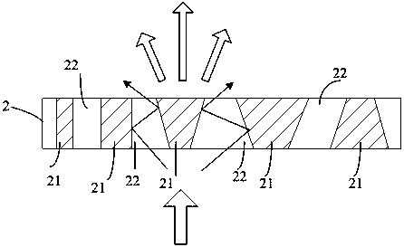
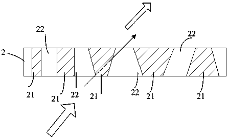
[0005] The technical problem to be solved by the embodiments of the present invention is to provide an optical film, a backlight module, and a display device, which can realize the diffusion of incident light at a small angle in the range of the outgoing angle, thereby solving the small problem caused by the existing microstructure enhancement sheet. The angle incident light is difficult to take out and utilize, so as to improve the front brightness of the surface light source and improve the utilization rate of light energy

Method used


Image

  • Optical film, backlight module and display device
  • Optical film, backlight module and display device
  • Optical film, backlight module and display device

Examples


Embodiment Construction

[0025] In order to make the object, technical solution and advantages of the present invention clearer, the present invention will be further described in detail below in conjunction with the accompanying drawings.

[0026] like Figure 1 to Figure 5 As shown, in Embodiment 1 of the present invention, an optical film provided by the inventor is arranged on the top of the diffusion sheet (not shown), including the enhancement sheet 1, and also includes: The light control film 2 on the side, and the light control film 2 is formed with a low refractive index part 21 and a high refractive index part 22 whose refractive index is higher than the low refractive index part 21; wherein, the low refractive index part 21 adopts The material includes polymethyl methacrylate PMMA, polyethylene and polyvinyl chloride; the material used in the high refractive index part 22 includes polycarbonate PC and polyethylene terephthalate PET;

[0027] A corresponding distance is reserved between adj...


PUM


Abstract

The present invention provides an optical film disposed above a diffusion sheet. The optical film includes a brightness enhancement sheet and further comprises: a light control film disposed on the side, facing the diffusion sheet, of the brightness enhancement sheet; low refractive index portions and high refractive index portions having a higher refractive index than the low refractive index portions are formed on the light control film; the low refractive index portions are disposed adjacent to one another with a corresponding spacing distance; and the high refractive index portions are disposed in the gaps between the adjacent low refractive index portions; the high refractive index portion within each gap is capable of reflecting incident light having an angle lower than a predetermined angle from the diffusion sheet to the brightness enhancement sheet into outgoing light having an angle within a limited range and directly transmitting incident light having an angle higher than the predetermined angle. According to the invention, incident light with a small angle can be diffused in the range of an exit angle, so that the problem that small-angle incident light cannot be takenout and utilized because of the conventional microstructure brightness enhancement sheet is solved and the purpose of improving the front brightness of a surface light source and improving the utilization of light energy can be achieved.

Description

technical field [0001] The invention relates to the field of display technology, in particular to an optical film, a backlight module and a display device. Background technique [0002] Mini-LED surface light sources are often made into flexible display backlights, and because of the display advantages of narrow bezels in full-screen display technology, they are often made into heterogeneous backlights for heterogeneous display fields, making Mini-LED surface light sources become the current display industry. one of the key areas of research. [0003] Mini-LED surface light source is mainly composed of Mini-LED light source, light guide plate, optical film, plastic frame, etc. It is often used to provide reliable light source for display panels because of its high brightness, long life, and uniform light emission. In the Mini-LED surface light source, after the light emitted by the Mini-LED light source enters the light guide plate, the light is evenly taken out through the...

Claims


Application Information

Patent Timeline
Patent Type & Authority Applications(China)
IPC IPC(8): G02B5/02G09F9/30
CPCG02B5/02G09F9/301
Inventor 杨勇
Owner WUHAN CHINA STAR OPTOELECTRONICS TECH CO LTD
Learn More