Protecting device with heat dissipation function for electromechanical equipment

A technology for electromechanical equipment and protection devices, applied in substation/distribution device housing, substation/switchgear cooling/ventilation, substation/switch layout details, etc. Dust, air conditioner outdoor unit falling and other problems, to achieve the effect of convenient disassembly and installation, maintaining stability, and stable installation

Active Publication Date: 2018-11-23
兰州西驰电气有限公司
View PDF4 Cites 3 Cited by
  • Summary
  • Abstract
  • Description
  • Claims
  • Application Information

AI Technical Summary

Problems solved by technology

[0004] The purpose of the present invention is to provide a protective device for electromechanical equipment with heat dissipation function to solve the above-mentioned background technology. The existing protective device for electromechanical equipment is only a simple protective cover when protecting the external unit of the air conditioner. It has the effect of heat dissipation and dust prevention. In the hot summer, long-term use of the air conditioner external unit will seriously affect the service life of the air conditioner external unit. When installing the air conditioner external unit, it will be dangerous and the installation is not firm. In rainy and snowy weather in winter, there will be a lot of snow on the protective cover. When the general protective cover is used for a long time, the pressure bearing capacity will become worse and worse, causing the external unit of the air conditioner to fall, which is a very dangerous problem.

Method used


Image

  • Protecting device with heat dissipation function for electromechanical equipment
  • Protecting device with heat dissipation function for electromechanical equipment
  • Protecting device with heat dissipation function for electromechanical equipment

Examples


Embodiment Construction

[0030] The following will clearly and completely describe the technical solutions in the embodiments of the present invention with reference to the accompanying drawings in the embodiments of the present invention. Obviously, the described embodiments are only some, not all, embodiments of the present invention. Based on the embodiments of the present invention, all other embodiments obtained by persons of ordinary skill in the art without making creative efforts belong to the protection scope of the present invention.

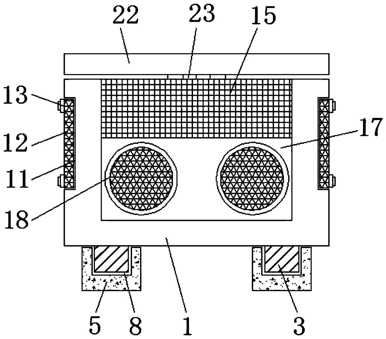
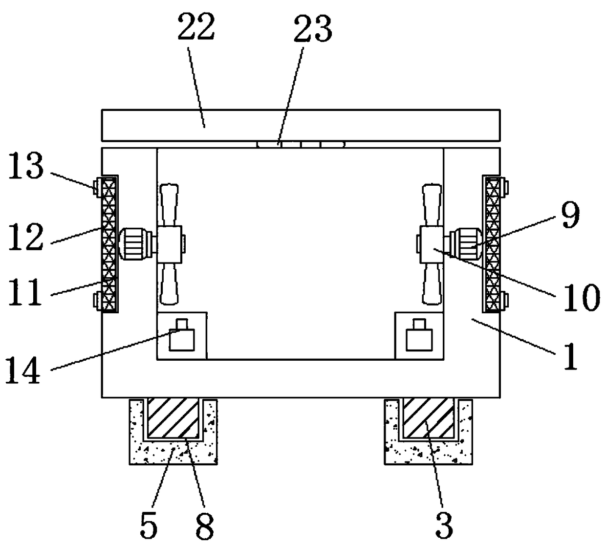
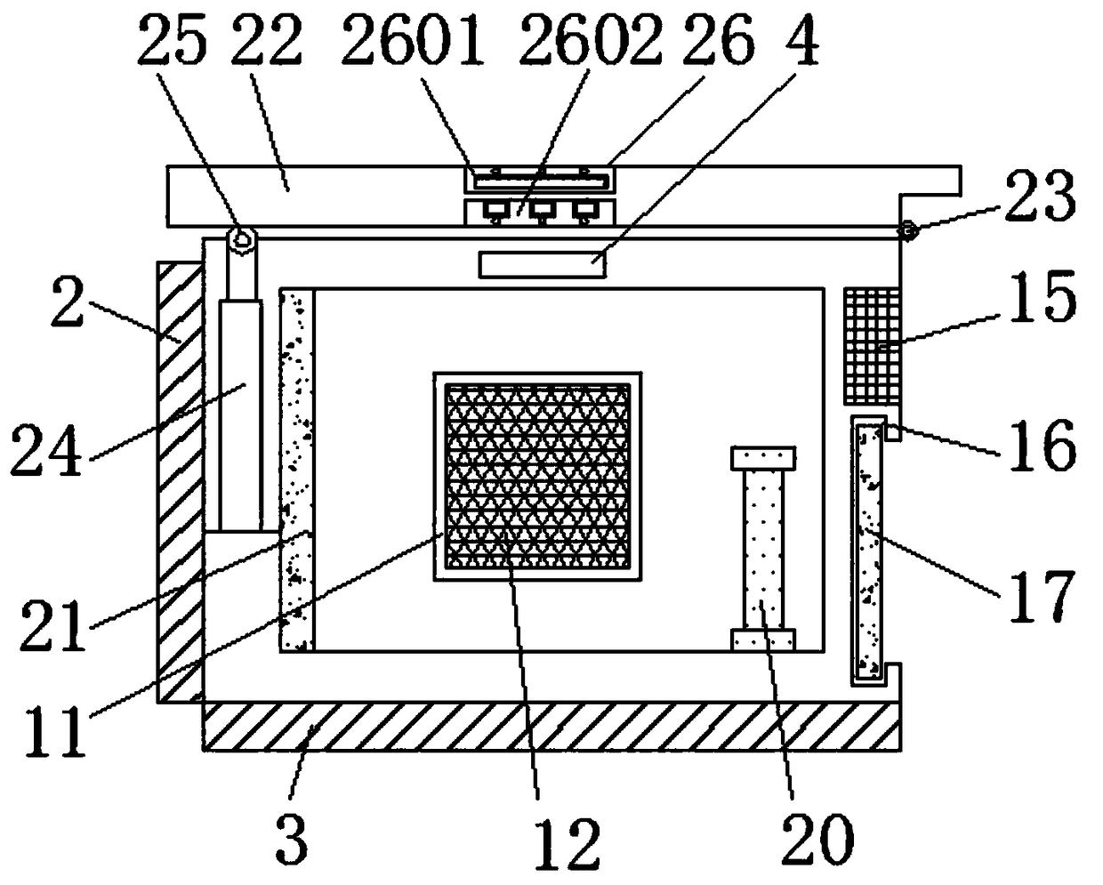
[0031] see Figure 1-9 , the present invention provides a technical solution: a protective device for electromechanical equipment with heat dissipation function, including a casing 1, a mounting plate 2, a support plate 3, a handle 4, a fixing frame 5, a mounting hole 6, a vertical groove 7, a bottom Slot 8, rotating motor 9, fan 10, heat dissipation side slot 11, ventilating dustproof net 12, bolt 13, battery 14, solar power generation panel 15, baffle slot 1...


PUM


Abstract

The invention discloses a protecting device with a heat dissipation function for electromechanical equipment. The protecting device comprises a shell, fixing frames and rotating motors. Mounting plates are fixed to the edge side of the shell. Mounting holes are reserved in the fixing frames. The rotating motors are fixed to the inner side of the shell. Air-permeable dustproof nets are mounted in heat dissipation lateral grooves. Storage batteries are fixed to the inner side of the bottom of the shell, and a baffle groove is formed in the bottom of the edge side of the shell. Air-permeable grooves are reserved on a sealing plate. A water pipe groove is formed in the inner wall of the shell, a sound absorption plate is mounted in the shell, a top cover is arranged at the upper end of the shell, and an electric push rod is mounted in the shell. According to the protecting device with the heat dissipation function for the electromechanical equipment, an air conditioner external unit is subjected to heat dissipation treatment through air cooling and water cooling, and the protecting device has a dustproof function while being convenient to demount and mount; and by arranging the electric push rod and the top cover, accumulated snow on the top cover can be automatically cleared, and the service life of the device is prolonged.

Description

technical field [0001] The invention relates to the technical field of protection devices for electromechanical equipment, in particular to a protection device for electromechanical equipment with a heat dissipation function. Background technique [0002] Mechanical and electrical equipment generally refers to machinery, electrical appliances, and electrical automation equipment. Among household appliances, air conditioners are the most common mechanical and electrical equipment in life. Withstand the wind and sun, so it is necessary to protect the external unit of the air conditioner. [0003] However, the existing protection devices for electromechanical equipment are just a simple protective cover when protecting the external unit of the air conditioner, which does not have the effect of heat dissipation and dust prevention. In the hot summer, long-term use of the external unit of the air conditioner will seriously affect The service life of the outdoor unit is dangerous...

Claims


Application Information

Patent Timeline
Patent Type & Authority Applications(China)
IPC IPC(8): H02B1/26H02B1/56
CPCH02B1/26H02B1/565
Inventor 王业送
Owner 兰州西驰电气有限公司
Why Eureka
Try Eureka