Anti-dropping tackle for electric transmission lines

A transmission line, anti-off technology, applied in the direction of overhead lines/cable equipment, etc., can solve problems such as deformation, spring replacement procedures, lock plate can not be locked, etc., to improve structural flexibility, prevent position deviation, and reliable The effect of the work environment

Inactive Publication Date: 2018-11-23
XICHUAN COUNTY POWER BUREAU
View PDF7 Cites 2 Cited by
  • Summary
  • Abstract
  • Description
  • Claims
  • Application Information

AI Technical Summary

Problems solved by technology

The disadvantage of this structure is that the hanger is a rectangular structure. When the opening side of the hanger is hung on the wire, the wire is easy to get stuck under the lock plate instead of directly falling into the opening of the hanger. In addition, the spring is located on the lock plate. On the outside and above the lock column, the spring designed with this structure has the problem of irreversible deformation during long-term use, which may easily cause the lock plate to fail to completely lock the opening of the hanger, and the spring replacement procedure is troublesome
The disadvantage of this structure is that when the wind is too strong, the wire will touch the tie rod. However, the strength of the tie rod structure is insufficient, and it is easy to deform, which affects the opening effect of the opening.

Method used


Image

  • Anti-dropping tackle for electric transmission lines
  • Anti-dropping tackle for electric transmission lines
  • Anti-dropping tackle for electric transmission lines

Examples


Embodiment 1

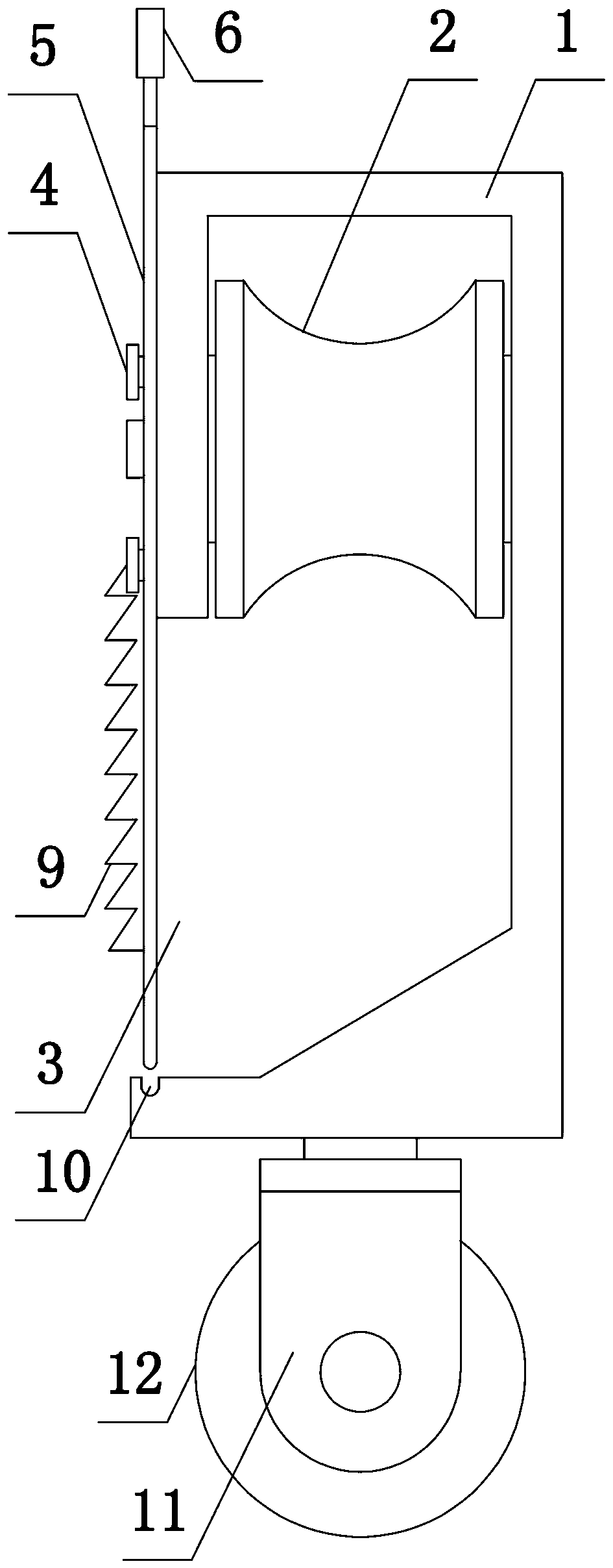
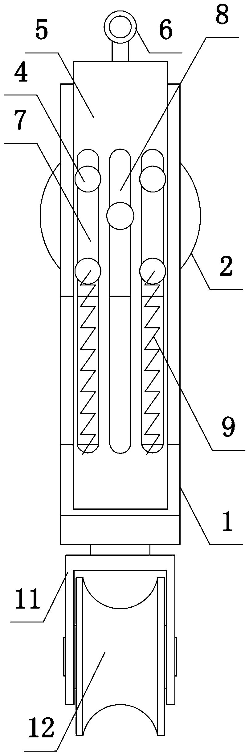
[0025] Such as figure 1 and figure 2 As shown, the present invention includes a hook 1, a suspension mechanism and a self-sealing mechanism. The first pulley 2 is installed in the hook 1, the hook 1 is provided with an opening 3, and the position of the hook 1 near the opening 3 is threaded to connect two sets of positioning columns 4, each group of positioning columns 4 is arranged in two along the vertical direction, and the self-sealing mechanism includes a sealing plate 5 and a lifting ring 6 welded on the upper end of the sealing plate 5, and two first elongated holes 7 and one second elongated hole 8 are opened on the sealing plate 5, Sliding fit between the positioning column 4 and the first elongated hole 7, the second elongated hole 8 provides a sliding space for the central axis of the first pulley 2, two springs 9 are fixed on the outer end surface of the sealing plate 5, and the other end of the spring 9 Fixedly connected with the positioning column 4, the hook 1...

Embodiment 2

[0027] The present invention comprises a hook 1, a suspension mechanism and a self-closing mechanism. A first pulley 2 is installed in the hook 1. An opening 3 is arranged on the hook 1. The position of the hook 1 close to the opening 3 is threaded to connect two sets of positioning columns 4, and each group of positioning columns 4 is connected vertically. The vertical direction is set to two, and the self-sealing mechanism includes a sealing plate 5 and a suspension ring 6 welded on the upper end of the sealing plate 5. Two first elongated holes 7 and a second elongated hole 8 are provided on the sealing plate 5, and the positioning column 4 Sliding fit with the first elongated hole 7, the third pulley is set between the sealing plate 5 and the positioning column 4, the second elongated hole 8 provides a sliding space for the central axis of the first pulley 2, and the outer end surface of the sealing plate 5 Two springs 9 are fixed, the other end of the spring 9 is fixedly c...


PUM


Abstract

The invention discloses an anti-dropping tackle for electric transmission lines. The anti-dropping tackle comprises a hook and a suspension mechanism, wherein a first pulley is installed in the hook.The hook is provided with an opening, a self-closing mechanism is arranged at the position, close to the opening, of the hook, and two sets of positioning columns are fixedly connected to the positions, close to the opening, of the hook. The self-sealing mechanism comprises an opening sealing plate and a lifting ring arranged at the upper end of the opening sealing plate, wherein the opening sealing plate is provided with two first long strip holes and a second long strip hole. The positioning columns are slidably matched with the first long strip holes, and the second long strip hole providessliding space for a central shaft of the first pulley. Two springs are fixed to the outer end face of the opening sealing plate, and the positioning columns are fixedly connected to the other ends ofthe springs. According to the anti-dropping tackle, the opening sealing mechanism adopts a plate like structure, the failure of the opening sealing mechanism caused by the collision between wires andthe opening sealing plate in the running process of a tackle is effectively prevented, and a stable and reliable working environment for aerial work is provided.

Description

technical field [0001] The invention belongs to the technical field of electric power equipment, in particular to a detachment-preventing pulley for transmission lines. Background technique [0002] At present, most of the overhead transmission lines in my country are located in the wilderness and suburbs. The electrical part of the line is affected by electromechanical, climate and environmental pollution. Ground wires, insulators, and fittings are prone to defects such as broken strands, insulator zero value or self-explosion, and fittings corrosion. . With the development of our country's economy, all sectors of the national economy, including people's daily electricity consumption, have put forward the requirements for continuous and reliable power supply. In order to prevent power supply enterprises from stopping power supply due to equipment experiments, maintenance and processing equipment defects, causing losses to industrial and agricultural production and causing t...

Claims


Application Information

Patent Timeline
Patent Type & Authority Applications(China)
IPC IPC(8): H02G1/02
CPCH02G1/02
Inventor 王媛媛张清李怀生全海建邓蕊邢炜垠肖冉梁澜金燕平全朝旭
Owner XICHUAN COUNTY POWER BUREAU
Why Eureka
Try Eureka