High-performance large span cable bridge

A cable tray and large-span technology, applied in the direction of electrical components, can solve problems such as confusion, difficult placement, and influence on cable maintenance and repair, and achieve the effects of neat placement, increased quantity, and easy maintenance and repair

Inactive Publication Date: 2018-11-23
江苏中讯电力科技有限公司
View PDF7 Cites 1 Cited by
  • Summary
  • Abstract
  • Description
  • Claims
  • Application Information

AI Technical Summary

Problems solved by technology

The existing large-span cable tray has a single structure, and the width of the cable tray is fixed. When a large number of cables need to be placed in the cable tray, it is not only difficult to place, but also easy to cause confusion, which affects the later maintenance and repair of cables.

Method used


Image

  • High-performance large span cable bridge
  • High-performance large span cable bridge
  • High-performance large span cable bridge

Examples


Embodiment 1

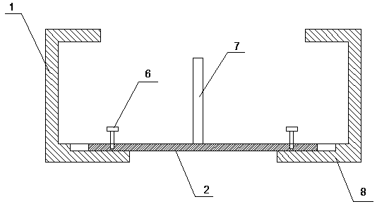
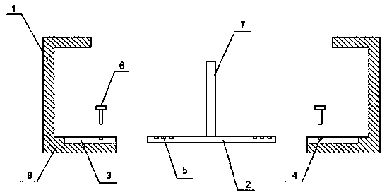
[0029] This embodiment provides a high-performance long-span cable bridge, including a bridge body, and the bridge body includes two opposite ladder sides 1 and a horizontal plate 2 installed between the two ladder sides 1, and the lower end of each ladder side 1 is There is a horizontal folded edge 8, and the end of the folded edge 8 close to the horizontal plate 2 is provided with a horizontal clamping groove 3, and the left and right sides of the horizontal plate 2 are slidingly arranged in the clamping grooves 3 of the two ladder sides 1 respectively. Adjusting the width of the horizontal plate 2 extending into the card slot 3 can adjust the distance between the two ladder sides 1 .

[0030] On the horizontal plate 2, the left side and the right side are respectively provided with three limiting holes one 4, and these limiting holes one 4 are evenly arranged along the width direction of the horizontal plate 2, and the clamping groove 3 is provided with two limiting holes 5,...

Embodiment 2

[0038] This embodiment provides a high-performance long-span cable bridge, including a bridge body, and the bridge body includes two opposite ladder sides 1 and a horizontal plate 2 installed between the two ladder sides 1, and the lower end of each ladder side 1 is There is a horizontal folded edge 8, and the end of the folded edge 8 close to the horizontal plate 2 is provided with a horizontal clamping groove 3, and the left and right sides of the horizontal plate 2 are slidingly arranged in the clamping grooves 3 of the two ladder sides 1 respectively. Adjusting the length of the horizontal plate 2 extending into the card slot 3 can adjust the distance between the two ladder sides 1 .

[0039]On the horizontal plate 2, the left side and the right side are respectively provided with three limiting holes one 4, and these limiting holes one 4 are evenly arranged along the width direction of the horizontal plate 2, and the clamping groove 3 is provided with two limiting holes 5,...

Embodiment 3

[0047] This embodiment provides a high-performance long-span cable bridge, including a bridge body, and the bridge body includes two opposite ladder sides 1 and a horizontal plate 2 installed between the two ladder sides 1, and the lower end of each ladder side 1 is There is a horizontal folded edge 8, and the end of the folded edge 8 close to the horizontal plate 2 is provided with a horizontal clamping groove 3, and the left and right sides of the horizontal plate 2 are slidingly arranged in the clamping grooves 3 of the two ladder sides 1 respectively. Adjusting the length of the horizontal plate 2 extending into the card slot 3 can adjust the distance between the two ladder sides 1 .

[0048] On the horizontal plate 2, the left side and the right side are respectively provided with three limiting holes one 4, and these limiting holes one 4 are evenly arranged along the width direction of the horizontal plate 2, and the clamping groove 3 is provided with two limiting holes 5...


PUM


Abstract

The invention discloses a high-performance large span cable bridge, comprising a bridge body, wherein the bridge body comprises a pair of ladder edges and a horizontal plate installed between the ladder edges, the lower ends of the ladder edges are provided with horizontal clamping slots, and the left and right sides of the horizontal plate are slidably arranged in the clamping slots of the two ladder edges respectively. The invention also discloses a preparation method of the high-performance large span cable bridge. According to the scheme of the invention, by adjusting the width of the partof the horizontal plate inside the clamping slots, the distance between the two ladder edges can be adjusted, so that the width of the cable bridge can be adjusted, the number and size of the cablesto be placed can be adjusted to meet higher use requirements, and moreover, the high-performance large span cable bridge prepared by the invention has the advantages of light weight, high strength andlong service life.

Description

technical field [0001] The invention relates to the technical field of cable bridges, in particular to a high-performance long-span cable bridge. Background technique [0002] Cable tray is a cable laying device that can standardize, systematize, and generalize the laying of wires, cables, and pipe cables. Its basic types include the following: trough cable tray, a fully enclosed cable tray, which is most suitable for Laying of computer cables, communication cables, thermocouple cables and other highly sensitive system control cables has good shielding interference and cable protection in heavy corrosion environments; the tray type cable tray has light weight, large load, and shape It has the advantages of beautiful appearance, simple structure, and convenient installation. It is suitable for the installation of power cables and the laying of control cables; the stepped cable tray is suitable for laying cables with large diameters, especially for high and low power cables. ...

Claims


Application Information

Patent Timeline
Patent Type & Authority Applications(China)
IPC IPC(8): H02G3/04C08L63/00C08L61/06C08L67/02C08K13/04C08K7/14C08K3/22C08K5/13
CPCH02G3/0437C08L63/00C08L2205/03C08L61/06C08L67/02C08K13/04C08K7/14C08K3/22C08K5/13
Inventor 陈龙陈超
Owner 江苏中讯电力科技有限公司
Why Eureka
Try Eureka