a motor

A magnetic pole and rotor technology, applied in the field of motor equipment, can solve the problems of weakening the electromagnetic pull of the motor rotor, reducing the heating loss of the winding, reducing the motor, etc., achieving a stable and quiet working state, reducing noise, and reducing the winding space.

Active Publication Date: 2021-04-13
昆明安索科技有限公司
View PDF3 Cites 0 Cited by
  • Summary
  • Abstract
  • Description
  • Claims
  • Application Information

AI Technical Summary

Problems solved by technology

[0003] In order to overcome the problems in the background technology, the present invention discloses a motor comprising a rotor and a stator, the stator comprises two stator cores, each stator core wraps a pair of adjacent magnetic poles, and each magnetic pole includes an opposite At the front and rear ends of the rotor rotation direction, wedge-shaped protrusions are added to the front side of the magnetic poles. Compared with the opposite magnetic poles of a single stator core, the adjacent magnetic poles of two stator cores can provide greater torque and lower speed. It is beneficial to expand the application occasions of the motor. The two stator cores are arranged opposite to each other, so that the four magnetic poles are perpendicular to each other and the windings are evenly arranged on both sides of the rotor, which can greatly weaken the lateral electromagnetic pull of the motor rotor, making the motor run more smoothly and quietly, and reduce noise. In order to provide a more stable and quiet working state, when the rotation direction of the motor is fixed, by adding wedge-shaped protrusions at the front end of the magnetic pole, it can effectively avoid magnetic saturation at the front end, and without adding wedge-shaped protrusions at the rear end can reduce the adjacent stator core. The increase of magnetic flux leakage between magnetic poles makes the output power of the motor higher and more efficient. Each magnetic pole corresponds to a mechanical angle of at least 60°, which can better attract the magnetic flux generated by the permanent magnet rotor, but the mechanical angle does not exceed 85° to avoid leakage. The aggravation of the magnetic phenomenon, the triangular stator core with slot opening can make the winding easier to wind on the stator core, the triangular area inside the triangular stator core provides a large gap so that the winding has a large winding space to reduce the winding Heat loss, so as to obtain higher motor efficiency, the gap between the two triangular stator cores can be used to place capacitors in the motor control circuit, reducing the overall volume of the motor and improving the compactness of the structure

Method used


Image

  • a motor
  • a motor
  • a motor

Examples


Embodiment Construction

[0019] In order to make the above objectives, technical solutions and beneficial effects clearer, the present invention will be described in detail below in conjunction with the accompanying drawings.

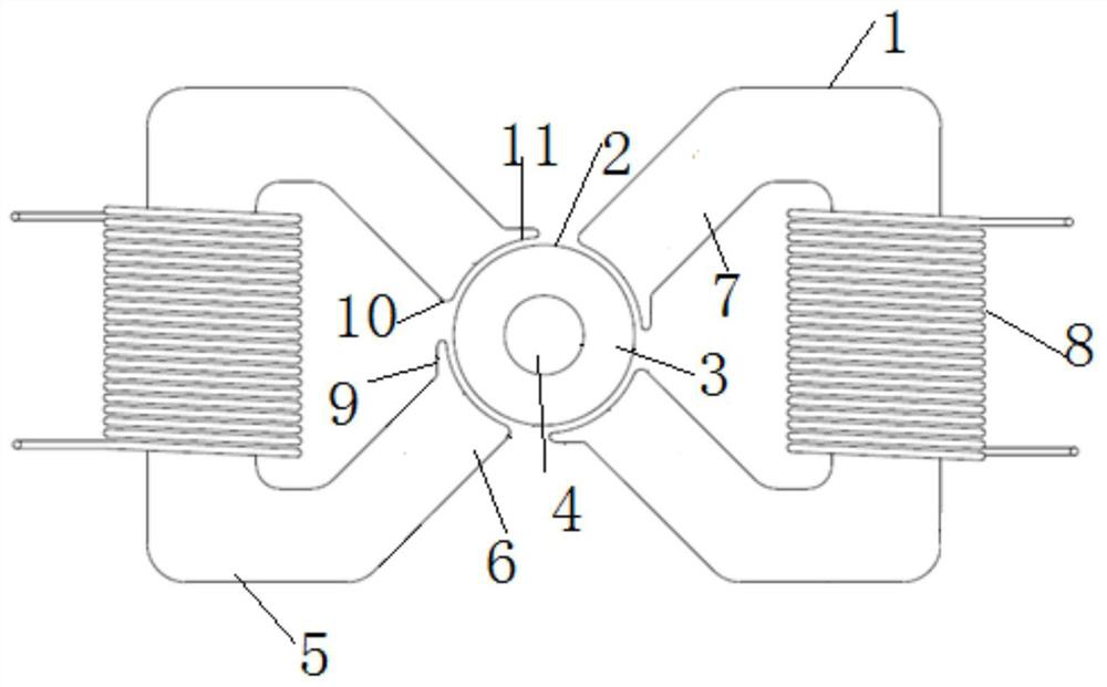
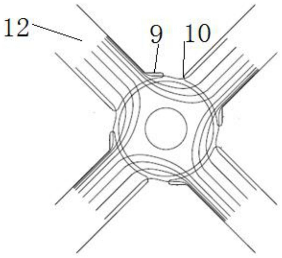
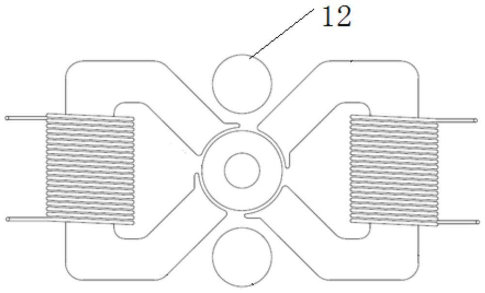
[0020] Such as figure 1 As shown, the motor includes a rotor 2 and a stator 5, the rotor 2 includes a four-pole annular permanent magnet 3 supported on a central shaft 4, the stator 5 includes a stator core 6 and a winding 8 wound on the stator core , the stator core 6 is a triangular shape with a slot opening, including the back and the adjacent magnetic poles 7 separated by the slot opening, the angle between the central axes of two adjacent magnetic poles 7 is 90 degrees, and the four magnetic poles 7 are perpendicular to each other, which can be greatly improved. Weaken the lateral electromagnetic pull of the rotor 2, so that the motor runs smoothly and with low noise. The windings 8 are respectively wound on the back of the stator core 6. Each magnetic pole 7 has a magneti...


PUM


Abstract

The invention relates to a motor, which belongs to the field of motor equipment. The motor mainly includes a rotor and a stator. The stator is composed of two stator cores and windings wound on the stator cores. Each stator core has two phase For adjacent magnetic poles, the central axes of the two adjacent magnetic poles are perpendicular to each other, and each magnetic pole is divided into a front end and a rear end along the direction of rotation relative to the rotor, and there is a wedge-shaped protrusion on the side of the front end.

Description

Technical field: [0001] The invention belongs to the technical field of motor equipment, in particular, the invention relates to a motor. Background technique: [0002] Conventional motors generally include a stator and a rotor. The stator includes a stator core wound with windings. The stator core includes two opposite magnetic poles arranged on both sides of the rotor. The motor with this structure is only suitable for high speed and low torque requirements, and the output torque of the motor is relatively low. Small, when four magnetic pole structures are used, there is the problem of insufficient winding space for windings, and because the windings are distributed on the same side of the rotor, the lateral electromagnetic pull is relatively large, and the noise and vibration are obvious during operation. When the rotor is at the maximum At the torque position, magnetic saturation occurs at the edge of the magnetic pole. In order to avoid magnetic saturation, the edge can...

Claims


Application Information

Patent Timeline
Patent Type & Authority Patents(China)
IPC IPC(8): H02K1/12H02K1/27
CPCH02K1/12H02K1/2706H02K2213/03
Inventor 王思奥
Owner 昆明安索科技有限公司
Why Eureka
Try Eureka