
Automatic wire winding equipment

A wire take-up device and automatic technology, applied in the field of automatic wire take-up equipment, to achieve high accuracy and improve the efficiency of wire take-up

Pending Publication Date: 2018-11-27
上海颐尚电气科技股份有限公司
View PDF0 Cites 7 Cited by
  • Summary
  • Abstract
  • Description
  • Claims
  • Application Information

AI Technical Summary

Problems solved by technology

However, since the copper wires will be wound side by side on many layers of wire reels, the existing winding methods (manual winding or simple winding devices) are difficult to ensure that the copper wires are wound neatly and efficiently on the wire reels

Method used


Image

  • Automatic wire winding equipment
  • Automatic wire winding equipment
  • Automatic wire winding equipment

Examples


Embodiment Construction

[0064] The present invention is described in detail below in conjunction with the accompanying drawings:

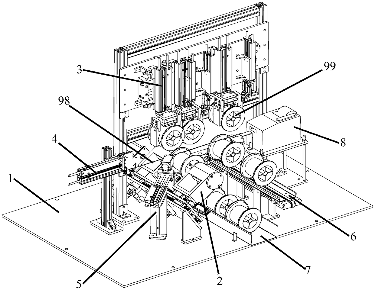
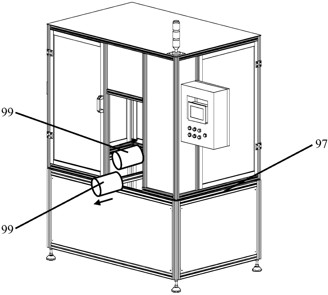
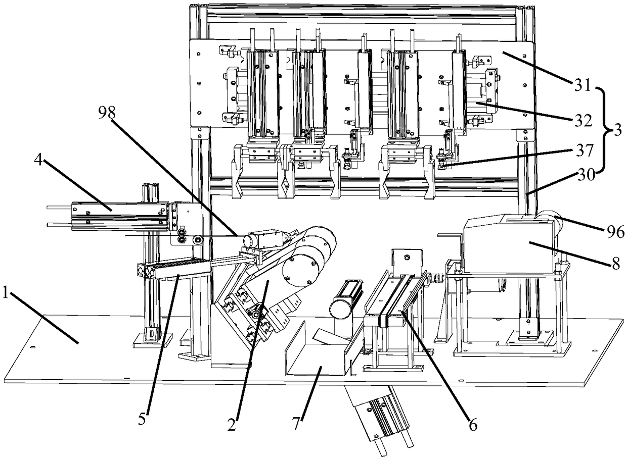
[0065] combine Figure 1 to Figure 4 As shown, the present invention firstly discloses an automatic wire take-up device comprising: a basic installation surface 1, preferably a base plate as the basic installation surface;

[0066] The winding mechanism 2 is installed on the basic installation surface 1 to clamp the bobbin 99 in the axial direction. The winding mechanism 2 drives the bobbin 99 to rotate, and the winding mechanism 2 drives the shaft. At the same time of rotation, the whole mechanism can move back and forth at a constant speed along the axis direction;

[0067] The clamping mechanism 3 is mounted on the base mounting surface 1 and includes a first side away from the winding mechanism 2 and a second side adjacent to the winding mechanism 2 , and the bobbin 99 passes through the The clamping mechanism 3 is clamped to the winding mechanism 2 from the first s...


PUM


Abstract

The invention discloses automatic wire winding equipment which comprises a wire winding mechanism, a clamping mechanism, a wire conveying mechanism and a cutting mechanism. The wire winding mechanismis used for axially moving to clamp a wire coil, drives the wire coil to pivot and can be in constant-speed reciprocating displacement along the direction of axis integrally when driving pivoting, theclamping mechanism comprises a first side away from the wire winding mechanism and a second side close to the wire winding mechanism, and the wire coil is clamped and sent to the wire winding mechanism from the first side through the clamping mechanism; the wire conveying mechanism is close to the second side and constantly conveys wires to the wire winding mechanism along the circumferential face of the outer wall of the clamped wire coil, and the cutting mechanism is used for cutting the wires. The automatic wire winding equipment can wind the wires on a calendering production line onto thewire coil orderly, efficiently and automatically.

Description

technical field [0001] The invention belongs to the technical field of wire winding, in particular to an automatic wire winding device. Background technique [0002] As we all know, wire rods need to be rolled up and stored after production and use to avoid scattered stacking and unified management. For example, for electric wires and cables, cable winders and transmission winders are often used to wind wires and cables of various sizes; for communication pipeline optical cables, pipeline winders are often used to wind up in a mechanically controlled manner. will be stored on the take-up reel. [0003] In the calendering production line, the copper wire is rolled by a calender, and then the copper wire is wound on a spool or a rotating shaft. However, since many layers of copper wires are wound side by side on the spool, the existing winding methods (manual manual winding or simple winding device) are difficult to ensure that the copper wire is wound on the spool neatly an...

Claims


Application Information

Patent Timeline
Patent Type & Authority Applications(China)
IPC IPC(8): B21C47/14B21C47/24B21C47/26B21C47/28B21C47/34
CPCB21C47/14B21C47/24B21C47/247B21C47/26B21C47/28B21C47/34
Inventor 赵昱圣赵军
Owner 上海颐尚电气科技股份有限公司
Learn More