A clamping device for a thin part of a watch

A clamping device and thin technology, applied in the field of clamping thin parts, can solve the problems of poor practicability and the influence of machining accuracy

Inactive Publication Date: 2018-11-27
ANHUI UNIVERSITY OF TECHNOLOGY AND SCIENCE
View PDF5 Cites 4 Cited by
  • Summary
  • Abstract
  • Description
  • Claims
  • Application Information

AI Technical Summary

Problems solved by technology

[0004] Aiming at the deficiencies in the prior art, the purpose of the present invention is to provide a clamping device for thin watch parts, so as to solve the problem that excessive dust absorbed on

Method used


Image

  • A clamping device for a thin part of a watch
  • A clamping device for a thin part of a watch
  • A clamping device for a thin part of a watch

Examples


Embodiment Construction

[0024] In order to make the technical means, creative features, goals and effects achieved by the present invention easy to understand, the present invention will be further described below in conjunction with specific embodiments.

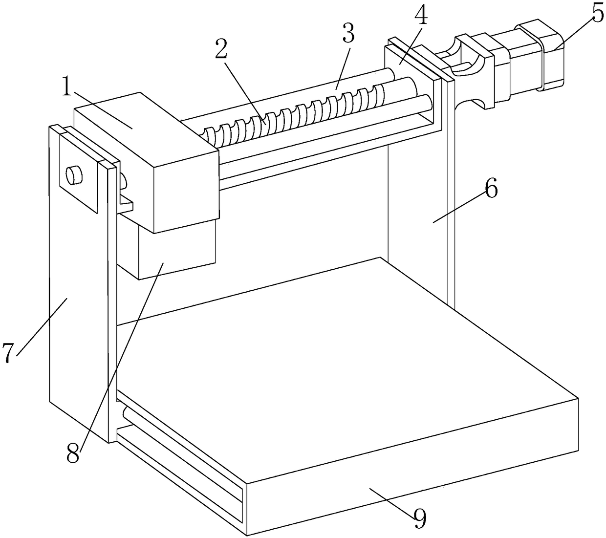
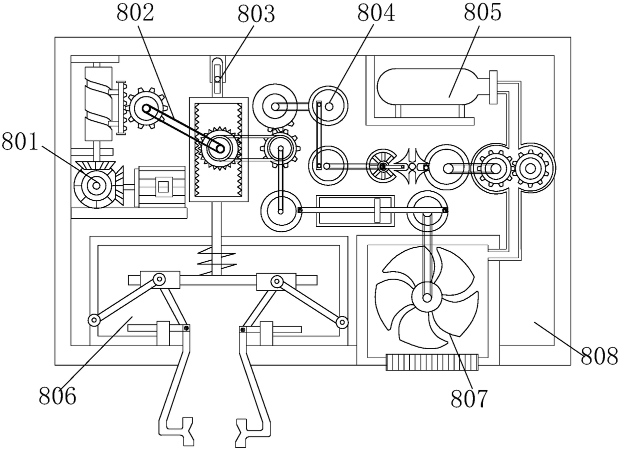
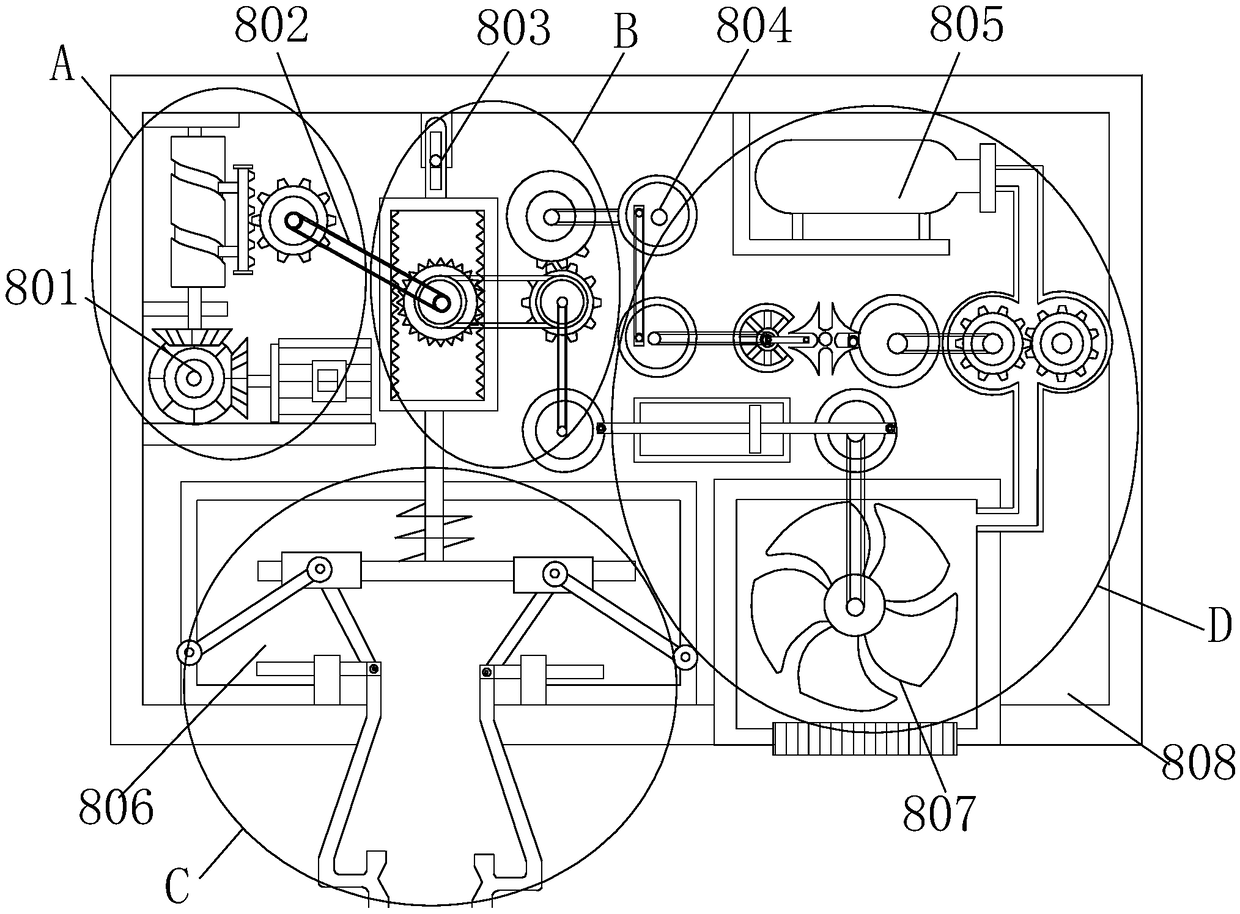
[0025] see Figure 1-Figure 7 , the present invention provides a technical solution for a clamping device for thin watch parts: a clamping device for thin watch parts, the structure of which includes a transverse sliding block 1, a transverse screw 2, a transverse guide roller 3, a transverse sliding seat 4, a first Motor 5, first sliding support plate 6, second sliding support plate 7, clamping device 8, workbench 9, the clamping device 8 is connected to the lower end surface of the horizontal sliding block 1, and the horizontal sliding seat 4 is horizontally Through the transverse sliding block 1, the transverse screw 2 and the transverse guide roller 3 are connected to the upper surface of the transverse sliding seat 4, and the left and right e...


PUM


Abstract

The invention discloses a clamping device for a thin part of a watch, the invention relates to a clamping device of a thin part of a watch, its structure includes transverse sliding block, transversescrew, transverse guide roll, transverse slide, First motor, first sliding support, second sliding support, clamping device, a worktable with a clamping device connected to the lower end surface of the transverse sliding block, A lateral slide seat penetrates that lateral slide block transversely, transverse screw, the transverse guide rollers are connected to the upper end surface of the transverse slide, the left and right ends of the transverse sliding seat are respectively connected with the second sliding support plate, first sliding support plate connection, one end of the first motor extends transversely through the first sliding support plate and is nested with the transverse sliding seat, The invention realizes that the device can clamp the watch thin part on the premise of preventing the watch thin part from deformation in the working process through the mutual combination of the parts, and can also effectively prevent the dust on the workbench from influencing the machiningaccuracy of the watch thin part in the next stage.

Description

technical field [0001] The invention relates to a clamping device for thin watch parts, which belongs to the technical field of clamping thin parts. Background technique [0002] Watch movements are assembled from hundreds of watch parts. In recent years, watches are developing towards luxury goods, and watch movements are also developing from low-end to high-end levels. The processing precision requirements are getting higher and higher. Especially in recent years, the variety of designs and colors of watch movements has been increasing, and the requirements for surface decoration and appearance of watch movements have become higher and higher. The whole plane milling, grinding, engraving, etc., these processes are all processing the entire upper plane of watch parts. [0003] When the prior art is in use, too much dust adsorbed on the workbench will affect the working environment of the equipment and the processing accuracy of the next stage of the watch's thin parts, and...

Claims


Application Information

Patent Timeline
IPC IPC(8): B23Q3/06B23Q11/00B24B41/06B24B55/06
CPCB23Q3/062B23Q11/005B24B41/068B24B55/06
Inventor 陈明珠吴娟胡子诺
Owner ANHUI UNIVERSITY OF TECHNOLOGY AND SCIENCE
Why Eureka
Try Eureka