Novel press-wheel type grinding fixture device

A technology of grinding jigs and pressure wheels, which is applied in the direction of grinding workpiece supports, etc., can solve the problems of low product qualification rate and increased processing costs of enterprises, and achieve the effects of good versatility, reduced processing costs, and reasonable positioning stability

Inactive Publication Date: 2018-11-27
JIANGSU FEIFAN INSTR
View PDF5 Cites 0 Cited by
  • Summary
  • Abstract
  • Description
  • Claims
  • Application Information

AI Technical Summary

Problems solved by technology

[0002] The shape of the workpiece produced in the machining oil nozzle pump industry is relatively small, and the material hardness is high, generally above 60HRC. Within 0.0005mm, the roundness of the cone surface is all within 0.0005mm, and it is mass-produced. The accuracy of the equipment and tooling must be guaranteed during the work process. Under the current situation, it cannot be guaranteed without high-precision special equipment, which limits The accuracy of domestic products cannot be guaranteed at the same level as the accuracy of foreign special equipment processing, which results in low product qualification rate and increased processing costs for enterprises

Method used


Image

  • Novel press-wheel type grinding fixture device
  • Novel press-wheel type grinding fixture device

Examples


Embodiment 1

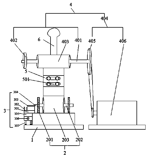
[0028] Such as Figure 1-2 As shown, a new press wheel type grinding fixture device includes a base plate 1 on which a support base 2, a workpiece placement device 3, and a workpiece pressing drive device 4 located above the support base 2 and the workpiece placement device 3 are provided. ;

[0029] The support base 2 includes support plates 201 arranged in parallel and a swing shaft 202 arranged between the support plates 201, the swing shaft 202 is rotatably connected in the swing block 203;

[0030] The workpiece placement device 3 includes a workpiece placement platform 301 fixedly connected to the base plate 1, a pair of vertical plates 302 arranged in parallel are fixed on one side of the upper end of the workpiece placement platform 301, and the vertical panels 302 arranged in parallel are symmetrically arranged with V-shaped The notch, the opposite side of the parallel vertical plate 302 and the workpiece placement platform 301 side are provided with a horizontal eje...

Embodiment 2

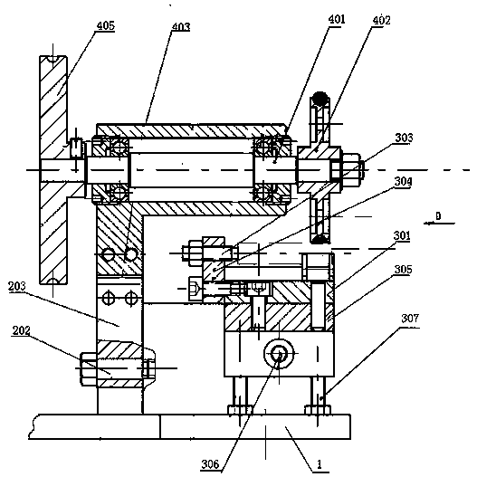
[0034] Such as figure 1 As shown, with respect to embodiment 1, the further improvement of embodiment 2 relative to embodiment 1 is that the bottom of the workpiece placement table 301 is fixed to the support seat 2 through the L-shaped plate 305, and the horizontal plate of the L-shaped plate 305 Fixed on the bottom of the workpiece placement table 301, the vertical plate of the L-shaped plate 305 is provided with a strip-shaped through hole, and the fixing bolt A306 passes through the strip-shaped through-hole and is fixed to the support seat 2; the vertical plate of the L-shaped plate 305 An adjusting rod 307 is arranged between the bottom of the straight plate and the top surface of the base plate 1. The adjusting rod 307 is an adjusting bolt, and the adjusting bolt passes through the threaded hole at the bottom of the L-shaped plate 305 to adjust. The top surface of the bottom plate 1 is in contact, and the adjustment rod (307) adjusts the height of the workpiece placemen...

Embodiment 3

[0037] Compared with Example 1, the further improvement of Example 3 relative to Example 1 is that the surface of the shaft sleeve 403 is fixed with a handle 6 for easy operation, and the base plate 1 is located on the workpiece placement table 301 facing away from the support seat 2 One side is fixed with a connecting rod, the handle 6 is arranged on the side of the shaft sleeve 403 facing the workpiece placement table 301, an elastic member is connected between the connecting rod and the handle 6, and the elastic member is provided with a pre-tension force, so The elastic member is an elastic rubber belt, so that the pressure roller 402 and the surface of the workpiece to be processed are kept in a good compression state;

[0038] All the other implementations are the same as in Example 1.


PUM


Abstract

The invention discloses a novel press-wheel type grinding fixture device, comprising a bottom plate, wherein a support seat, a workpiece placing device and a workpiece pressing driving device positioned above the support seat and the workpiece placing device are arranged on the bottom plate; The workpiece placement device comprises a workpiece placement table fixedly connected with a bottom plate,A pair of vertical plates arranged in parallel are fixed on one side of the upper end of the workpiece placement table, and on the opposite side of the parallel vertical plates, a horizontal ejectorrod perpendicular to the vertical plate is arranged on one side of the workpiece placement table, and the axial center of the horizontal ejector rod is coaxial with the axial center of the workpiece located on the vertical plate arranged in parallel; The workpiece pressing driving device comprises a horizontal rotating shaft parallel to the horizontal ejector bar, one end of the horizontal rotating shaft is fixed with a pressing wheel, and the pressing wheel is positioned above the parallel vertical plates. Through the reasonable positioning stability of the device and the stable rotation of the workpiece, qualified and stable quality products can be processed, and the processing cost can be greatly reduced.

Description

technical field [0001] The invention relates to a fixture device, in particular to a novel press wheel type grinding fixture device. Background technique [0002] The shape of the workpiece produced in the machining oil nozzle pump industry is relatively small, and the material hardness is high, generally above 60HRC. Within 0.0005mm, the roundness of the cone surface is all within 0.0005mm, and it is mass-produced. The accuracy of the equipment and tooling must be guaranteed during the work process. Under the current situation, it cannot be guaranteed without high-precision special equipment, which limits The accuracy of domestic products cannot be guaranteed to be at the same level as that of foreign special equipment, which results in low product qualification rates and increased processing costs for enterprises. Contents of the invention [0003] The main purpose of the present invention is to provide a new press wheel type grinding fixture device, through the setting...

Claims


Application Information

Patent Timeline
Patent Type & Authority Applications(China)
IPC IPC(8): B24B41/06
CPCB24B41/06
Inventor 孙家平岳齐
Owner JIANGSU FEIFAN INSTR
Why Eureka
Try Eureka