
Magnetic-energy-storage bicycle driving wheel

A technology for bicycles and driving wheels, which is applied in the direction of wheels, rider driving, vehicle components, etc., and can solve problems such as lack of assistance, easy fatigue, and strenuous riding for riders

Pending Publication Date: 2018-11-27
佛山市梦真营机电有限公司
View PDF0 Cites 6 Cited by
  • Summary
  • Abstract
  • Description
  • Claims
  • Application Information

AI Technical Summary

Problems solved by technology

When the bicycle is riding on flat ground or downhill, it is usually overcome by the inertia of the bicycle crank to move past the dead point naturally, but when the bicycle is riding at a slower speed or uphill, this problem is more prominent, due to the force at the dead point The direction is the same as the direction of the force arm, and the power moment is zero. The current transmission method makes it impossible to get power assistance at the "dead point" angle, causing the rider to feel strenuous and easily fatigued when riding

Method used


Image

  • Magnetic-energy-storage bicycle driving wheel
  • Magnetic-energy-storage bicycle driving wheel
  • Magnetic-energy-storage bicycle driving wheel

Examples


Embodiment Construction

[0025] The present invention provides a magnetic energy storage bicycle drive wheel. In order to make the purpose, technical solution and effect of the present invention clearer and clearer, the present invention will be further described in detail below with reference to the accompanying drawings and examples. It should be understood that the specific embodiments described here are only used to explain the present invention, not to limit the present invention.

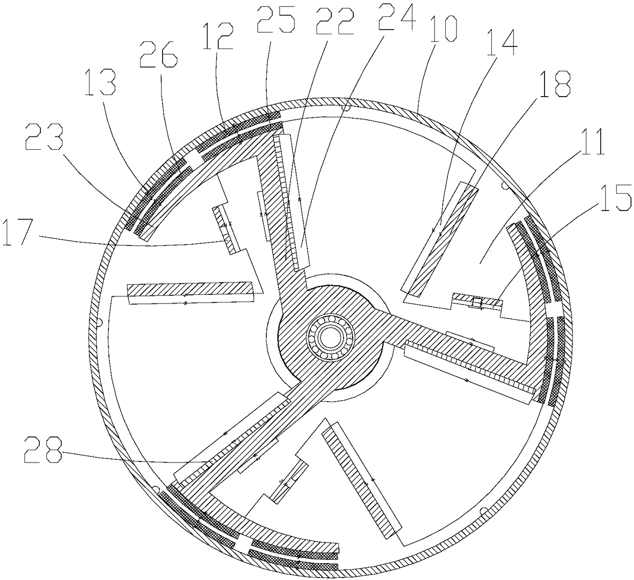
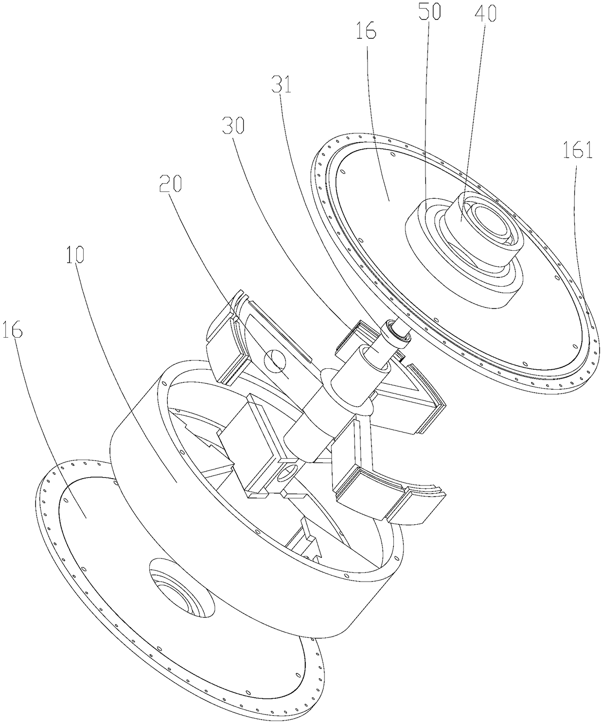
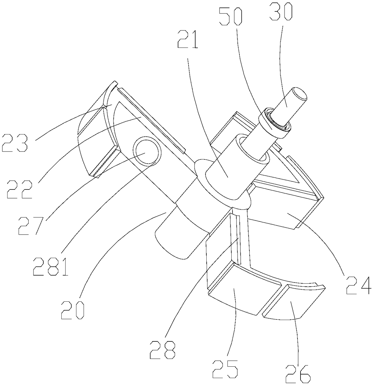
[0026] The drive wheel of a magnetic energy storage bicycle provided by the invention has the following structure: figure 1 , figure 2 , image 3 , Figure 4 shown, including:

[0027] The rim 10, the driving device 20 arranged in the rim 10, the axle skin 21 on the driving device 20, the wheel main shaft 30 nested in the center of the driving device 20, the first bearing arranged between the driving device 20 and the wheel main shaft 30 31. The second bearing 40 arranged between the end cover 16 and the driving ...


PUM


Abstract

The invention discloses a magnetic-energy-storage bicycle driving wheel. A driving device is arranged in a rim, driving permanent magnets are arranged on the driving device, and driven permanent magnets are arranged on the rim; after a user applies force during cycling, the driving permanent magnets and the driven permanent magnets mutually repel; the magnetic repelling force is compressed as thedistance gradually decreases; the driven permanent magnets are driven by human power to approach the driven permanent magnets gradually, magnetic energy is stored; after the magnetic repelling energythat is stored reaches a peak, namely, a crank is manually treaded to the bottom 'dead corner', the magnetic repelling force that is stored is automatically released in magnetic catapulting manner; the magnetic repelling energy that is stored is used to act on driven permanent magnet components in one step, so that accelerating kinetic energy applied to the rim; a hub is driven to accelerate to rotate; the wheel herein can be continually accelerated at the 'dead corner'; extended acceleration angle is imparted to the wheel; therefore, energy from manual cycling can be converted more efficiently, and cycling takes less manpower and is easier.

Description

technical field [0001] The invention relates to the field of bicycle accessories, in particular to a magnetic energy storage bicycle driving wheel. Background technique [0002] The bicycle is not only a green travel tool, but also a tool for physical exercise and fun. After a person rides on the bicycle, the pedals on the left and right sides of the bicycle are used as the input power to step on the pedals for 360°, that is, The external power drives the flywheel to rotate, and the flywheel drives the outer wheel of the rear wheel to rotate. However, the current method of direct transmission and variable speed transmission is used between the flywheel and the wheel of the bicycle, so that when a person is riding, the force of each angle of the pedal is consistent. , and the output of the human feet at various angles during the pedaling cycle is obviously uneven. The difference between the two makes the natural mismatch between the human and the vehicle, and the acceleration...

Claims


Application Information

Patent Timeline
Patent Type & Authority Applications(China)
IPC IPC(8): B62M1/10B62M6/00B60B19/00
CPCB62M1/10B62M6/00B60B19/006
Inventor 梁建华梁仕豪
Owner 佛山市梦真营机电有限公司
Learn More