
Method and system for collision and occlusion detection between virtual and real objects

A technology for occlusion detection and objects, applied in image data processing, instruments, etc., can solve problems such as poor tightness of bounding boxes, high hardware requirements, and heavy workload of point cloud data processing, and achieve the effect of short calculation time

Active Publication Date: 2018-11-27
QINGDAO TECHNOLOGICAL UNIVERSITY
View PDF8 Cites 20 Cited by
  • Summary
  • Abstract
  • Description
  • Claims
  • Application Information

AI Technical Summary

Problems solved by technology

[0004] Collision and occlusion detection based on the object space mostly use the depth camera to obtain the spatial point cloud of the real object, and replace the point cloud data processing with a bounding box or other proxy geometry to collide with the virtual object. This method requires a large amount of calculation and requires a computer. The hardware requirements are high, and at the same time, the workload of point cloud data processing in the early stage is large. If the bounding box is not well constructed, the tightness of the bounding box will be relatively poor, which will lead to false positives without collisions.
[0005] In summary, both estimating the pose of the object and constructing the bounding box model of the object require a lot of computing time, which is not suitable for real-time collision and occlusion detection of virtual and real models.

Method used


Image

  • Method and system for collision and occlusion detection between virtual and real objects
  • Method and system for collision and occlusion detection between virtual and real objects
  • Method and system for collision and occlusion detection between virtual and real objects

Examples


Embodiment 1

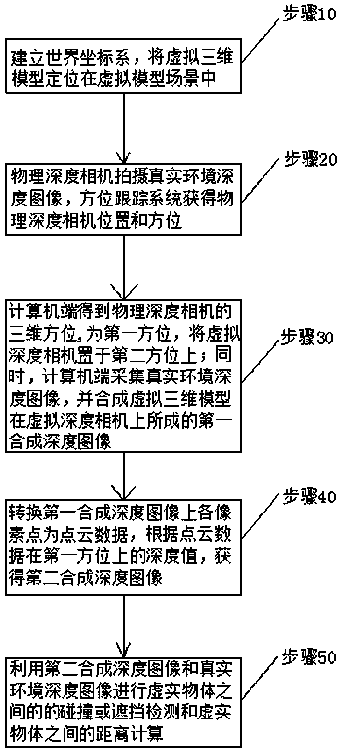
[0049] see figure 1 and figure 2 , a collision and occlusion detection method between virtual and real objects, comprising the following steps:

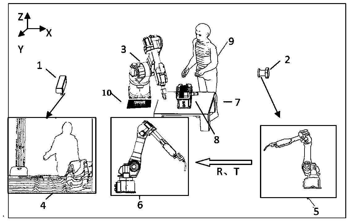
[0050] Step 10. Unify the computer-side virtual model scene coordinate system and the real environment coordinate system, so that both virtual and real objects are in the same world coordinate system, and then position the virtual 3D model 3 of the object to be detected (the virtual robot is taken as an example in the figure) in the In the virtual model scene on the computer side; this positioning can utilize methods such as augmented reality registration, for example, augmented reality registration card 10 can be used, and augmented reality registration card 10 is used as the world coordinate system to complete accurate positioning;

[0051] Step 20, in the real environment, the physical depth camera 1 captures the real environment depth image 4, and at the same time, uses the orientation tracking system to obtain the position and...

Embodiment 2

[0064] see figure 2 , figure 2 A real environment 7 including a reducer 8 to be assembled and its staff 9 is shown. A collision and occlusion detection system between virtual and real objects, including a physical depth camera 1, an azimuth tracking system and a computer system, the physical depth camera 1 takes a depth image of a real environment, and the azimuth tracking system acquires the physical depth of the physical depth camera 1 Position and orientation in the environment coordinate system; the physical depth camera 1 and the orientation tracking system are all connected to the computer system, and the depth image collected and the direction position tracked are transmitted to the computer system; please refer to Figure 7 , when the computer system is running, the following steps are implemented:

[0065] Step 1. Unify the computer-side virtual model scene coordinate system and the real environment coordinate system, so that both virtual and real objects are in t...


PUM


Abstract

The invention relates to a method for collision and occlusion detection between virtual and real objects. The method comprises: firstly, establishing a world coordinate system, and positioning a virtual three-dimensional model in a virtual model scene; secondly, using a physical depth camera to capture real environment depth images, and obtaining the position and azimuth of the physical depth camera by using an azimuth tracking system; thirdly, a computer obtaining three-dimensional orientation of the physical depth camera, defining the three-dimensional orientation as a first orientation; placing the virtual depth camera on a second orientation, and synthesizing a first synthetic depth image formed on the virtual depth camera by the virtual three-dimensional model according to the imagingmodel of the depth camera; calculating a depth value of each pixel point on the first synthetic depth image in the first orientation, to obtain a second synthetic depth image; finally, performing collision and occlusion detection and distance calculation of virtual and real objects by using the second synthetic depth image and the real environment depth image. The method is based on the depth image and rasterizes the depth image, and carries out collision and occlusion detection. The processing speed is fast and detection is accurate.

Description

technical field [0001] The invention relates to a method and system for collision interference detection and occlusion detection between a virtual three-dimensional model (generated by a computer) and a real object (physical environment), and belongs to the field of augmented reality and information-physical fusion systems. Background technique [0002] Augmented reality (Augmented Reality, AR) refers to the superimposition of computer-generated virtual models, virtual model scenes or virtual prompt information on real scenes, so as to realize the enhancement of the real environment. Augmented reality technology has the characteristics of combination of virtual and real, real-time interaction and three-dimensional registration. Among them, three-dimensional registration has always been the key technology of the augmented reality system, which refers to the accurate superimposition of the virtual model and the display on the real scene, so as to achieve the consistency of the...

Claims


Application Information

Patent Timeline
Patent Type & Authority Applications(China)
IPC IPC(8): G06T19/00
CPCG06T19/006
Inventor 陈成军张石磊李东年洪军
Owner QINGDAO TECHNOLOGICAL UNIVERSITY
Learn More