
Motor supporting structure and air purifier

A technology of motor support and motor body, applied in the direction of electrical components, casing/cover/support, electromechanical devices, etc., can solve the problems of easy deformation of the motor, high assembly process requirements, small bottom, etc., to reduce high requirements and layout Reasonable and compact effect

Active Publication Date: 2018-11-27
GREE ELECTRIC APPLIANCES INC OF ZHUHAI
View PDF4 Cites 0 Cited by
  • Summary
  • Abstract
  • Description
  • Claims
  • Application Information

AI Technical Summary

Problems solved by technology

[0002] At present, the motor fixing device in the air purifier is to form a housing slot for the motor from the inside of the air duct. The motor is placed from the inside, and then the motor fixing plate is placed. From the analysis of the molding principle of the injection molded part (involving mold release), The motor housing slot can only be small at the bottom and large at the end. The motor shaft center is adjusted through the motor fixing plate, which requires high assembly technology. In addition, after this method of assembly, the motor is easily deformed and shifted under the action of the gravity of the fan blade, causing Vibration noise, and there is a risk of damage to the fan blades

Method used


Image

  • Motor supporting structure and air purifier
  • Motor supporting structure and air purifier
  • Motor supporting structure and air purifier

Examples


Embodiment Construction

[0023] The present invention is described below based on examples, but the present invention is not limited to these examples. In the following detailed description of the invention, some specific details are set forth in detail. To avoid obscuring the essence of the present invention, well-known methods, procedures, procedures, and components have not been described in detail.

[0024] Additionally, those of ordinary skill in the art will appreciate that the drawings provided herein are for illustrative purposes and are not necessarily drawn to scale.

[0025] Unless the context clearly requires, throughout the specification and claims, "comprises", "comprises" and similar words should be interpreted in an inclusive sense rather than an exclusive or exhaustive meaning; that is, "including but not limited to" meaning.

[0026] In the description of the present invention, it should be understood that the terms "first", "second" and so on are used for descriptive purposes only...


PUM


Abstract

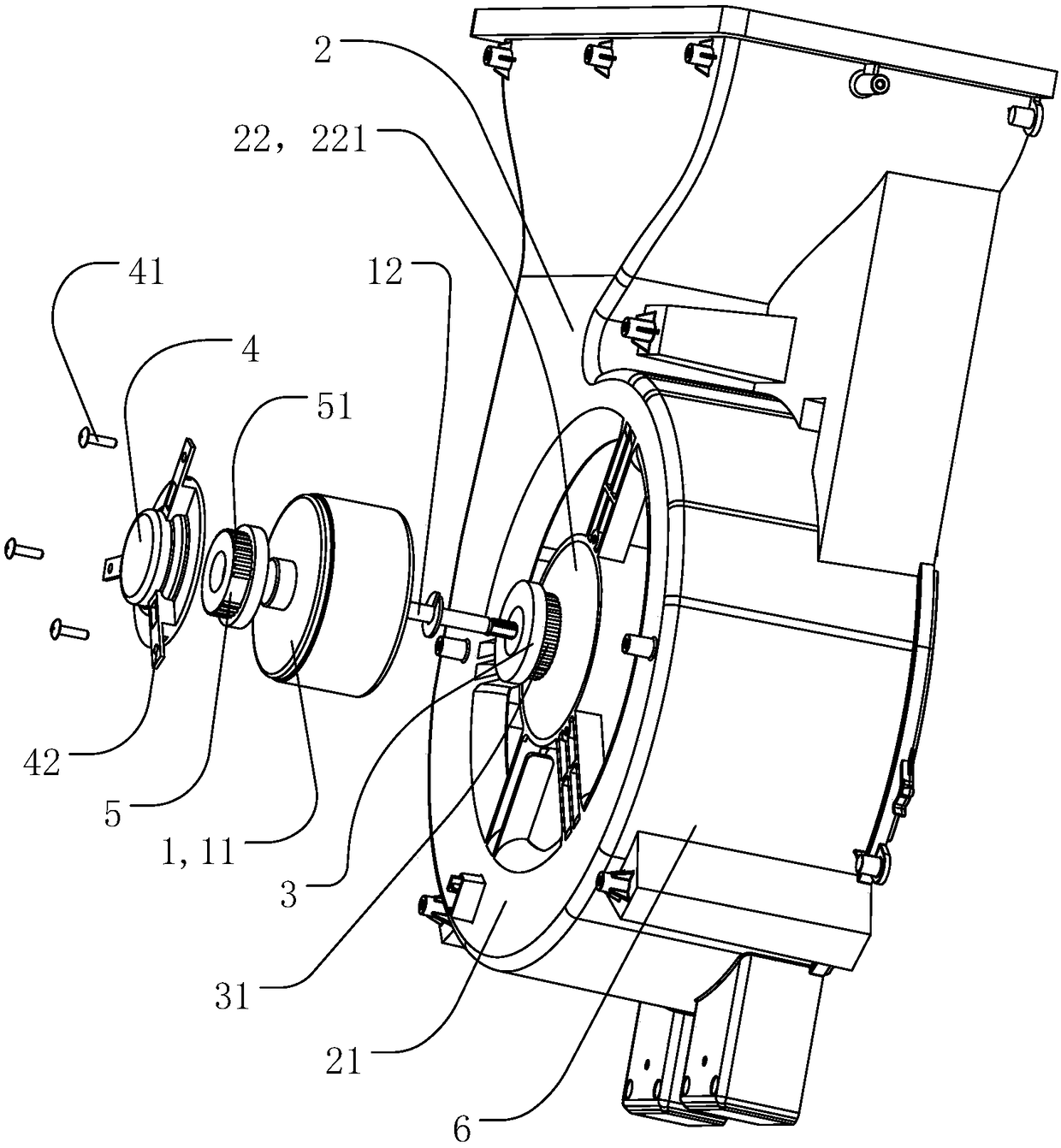
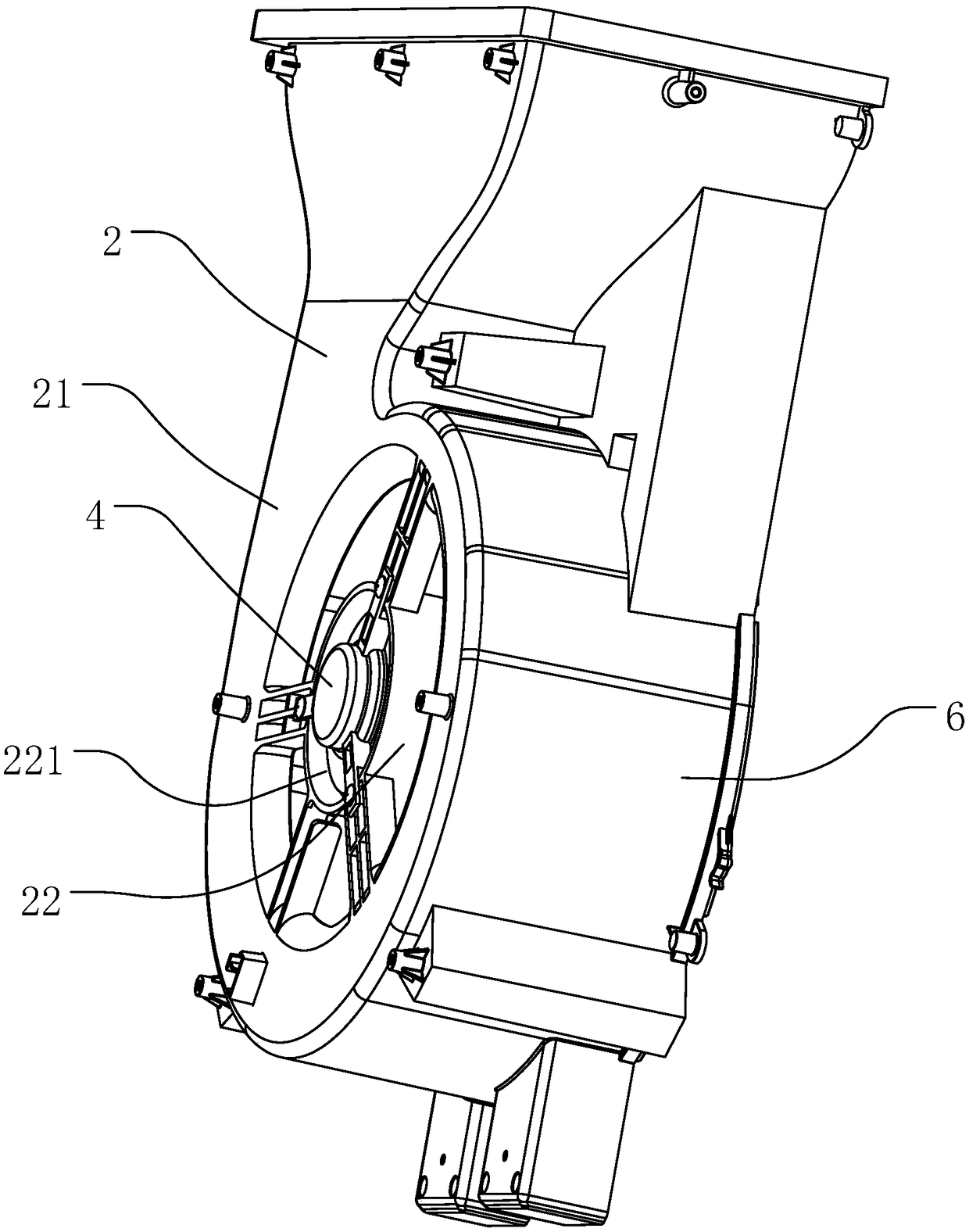
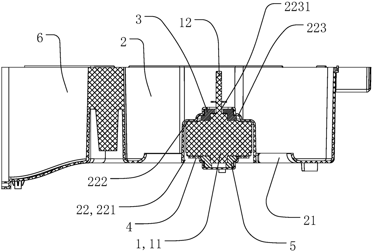
The invention relates to a motor supporting structure and an air purifier. The motor comprises a motor body and an output shaft. The motor supporting structure comprises a bearing part and a motor accommodating groove arranged on the bearing part, wherein the motor accommodating groove is used for accommodating the motor body, the bearing part is used for supporting the motor accommodating groove,the motor accommodating groove is in the shape of a cone, the large end of the cone is connected with the bearing part, and the output shaft is located at the side where the small end of the motor accommodating groove is located in an assembly state. The motor supporting structure realizes reliable assembly through changing the assembly direction of the motor, and the motor is put in from the outer side of an air duct, thereby reducing high requirements for the assembly process. Compared with the traditional structure scheme, the motor supporting structure is more reliable, compact in structure and reasonable in layout.

Description

technical field [0001] The invention relates to the technical field of electrical appliances, in particular to a motor support structure and an air purifier. Background technique [0002] At present, the motor fixing device in the air purifier is to form a housing slot for the motor from the inside of the air duct. The motor is placed from the inside, and then the motor fixing plate is placed. From the analysis of the molding principle of the injection molded part (involving mold release), The motor housing slot can only be small at the bottom and large at the end. The motor shaft center is adjusted through the motor fixing plate, which requires high assembly technology. In addition, after this method of assembly, the motor is easily deformed and shifted under the action of the gravity of the fan blade, causing Vibration noise, and there is a risk of damage to the fan blades. Contents of the invention [0003] In order to solve the problems existing in the background tech...

Claims


Application Information

Patent Timeline
IPC IPC(8): H02K5/04H02K5/24F24F3/16
CPCF24F3/16H02K5/04H02K5/24
Inventor 罗汉兵陈欢凌业生张帅劳承云朱露露吴志勇
Owner GREE ELECTRIC APPLIANCES INC OF ZHUHAI
Learn More