Motor car brake pipe end thermoforming device

A brake tube and thermoforming technology, applied in the direction of forming tools, manufacturing tools, metal processing equipment, etc., can solve the problems of inability to guarantee forging temperature, poor forming stability, increased manufacturing cycle and processing costs, etc., to achieve simple structure and improved Production efficiency and yield, and the effect of reducing manufacturing costs

Active Publication Date: 2018-11-30
JIANGNAN UNIV
View PDF7 Cites 0 Cited by
  • Summary
  • Abstract
  • Description
  • Claims
  • Application Information

AI Technical Summary

Problems solved by technology

Using this method requires the transfer of workpieces during processing, which cannot guarantee a good forging temperature, poor forming stability, and increases the manufacturing cycle and processing costs.

Method used


Image

  • Motor car brake pipe end thermoforming device

Examples


Embodiment Construction

[0017] Below the present invention will be further described in conjunction with the embodiment in the accompanying drawing:

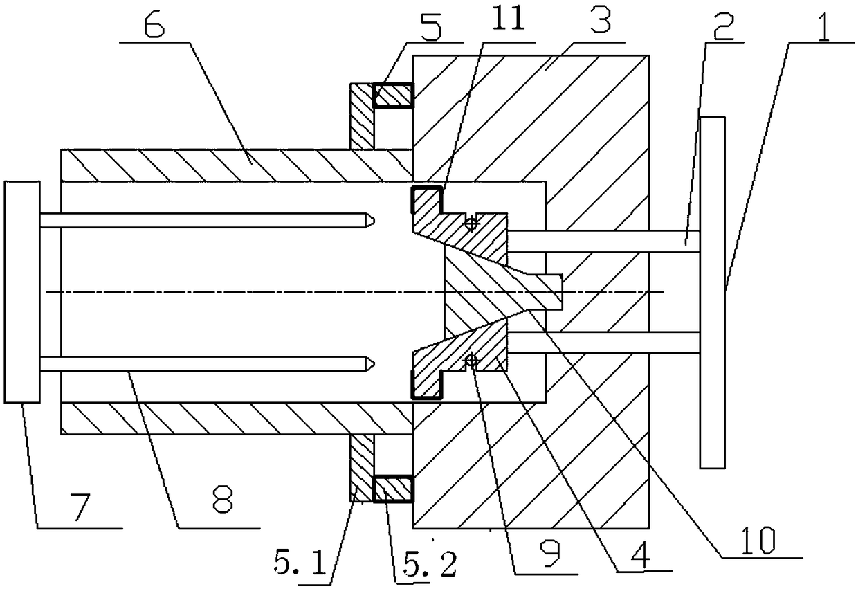
[0018] Such as figure 1 As shown, the present invention mainly comprises an anvil 3, a die 5, a bulging brace 10 and a punch assembly. The front end of the bulging support 10 is a conical truncated part, and the rear end is a mandrel part. The mandrel part of the bulging supporting part 10 is fixed in the center of the bulging supporting part installation cavity. department. During processing, a brake pipe 6 is placed between the die 5 and the punch assembly, and the end face of the brake pipe 6 is pressed against the front end face of the anvil 3 .

[0019] The die 5 includes a die energizing part 5.1 and a die insulating part 5.2. The die energizing part 5.1 is arranged vertically, and the die insulating part 5.2 is arranged horizontally. Die energizing part 5.1 is in contact with brake tube 6. Die energizing part 5.1 is made of conductive materia...


PUM


Abstract

The invention relates to a thermoforming device, in particular to a motor car brake pipe end thermoforming device, and belongs to the technical field of local thermoforming of tubular workpieces. Thethermoforming device comprises an anvil, a concave die, a bulging strut and a terrace die assembly. The front end surface of the anvil is fixedly provided with the concave die, the center of the anvilis provided with a bulging strut mounting cavity, the front end of the bulging strut is provided with a truncated cone portion, and the rear end is provided with a mandrel portion. The center of thebulging strut mounting cavity is fixedly provided with the mandrel portion of the bulging strut, and the terrace die assembly is connected to the truncated cone portion of the bulging strut in the front-back sliding mode. The thermoforming device is simple, compact and reasonable in structure and capable of thermoforming the end of a motor car brake pipe through one step, thereby improving the production efficiency and the yield of products and reducing the manufacturing cost.

Description

technical field [0001] The invention relates to a thermoforming device, in particular to a thermoforming device for the end of a motor vehicle brake pipe, which belongs to the technical field of partial thermoforming of tubular workpieces. Background technique [0002] At present, the thermoforming processing of the end of the brake pipe of the motor car is mainly divided into two steps: first, the end of the brake pipe of the motor car is rough-machined into a "garlic" shape by electric heating, and then the semi-formed end is forged on the forging equipment forming. Adopting this method needs to transfer the workpiece during the processing, which cannot guarantee a good forging temperature, poor forming stability, and increases the manufacturing cycle and processing cost. Contents of the invention [0003] The purpose of the present invention is to overcome the above disadvantages, thereby providing a thermal forming device for the end of the brake pipe of the motor veh...

Claims


Application Information

Patent Timeline
IPC IPC(8): B21D41/02B21D37/16
CPCB21D37/16B21D41/028
Inventor 任志俊梅荣王慧敏楼望阳庄瑾赵明光
Owner JIANGNAN UNIV
Why Eureka
Try Eureka