Patrolling robot mechanical arm tail end space positioning method

An inspection robot and spatial positioning technology, which is applied to manipulators, program-controlled manipulators, manufacturing tools, etc., can solve the problems of high cost of distance sensors and low positioning accuracy, so as to avoid low accuracy, reduce positioning costs, and improve spatial positioning accuracy. Effect

Inactive Publication Date: 2018-11-30
YUNNAN POWER GRID CO LTD KUNMING POWER SUPPLY BUREAU
View PDF9 Cites 8 Cited by
  • Summary
  • Abstract
  • Description
  • Claims
  • Application Information

AI Technical Summary

Problems solved by technology

[0004] The object of the present invention is: the present invention provides a spatial positioning method for the end of the manipulator of the inspection robot, which solves the problem

Method used


Image

  • Patrolling robot mechanical arm tail end space positioning method
  • Patrolling robot mechanical arm tail end space positioning method
  • Patrolling robot mechanical arm tail end space positioning method

Examples


Example Embodiment

[0044] Example 1

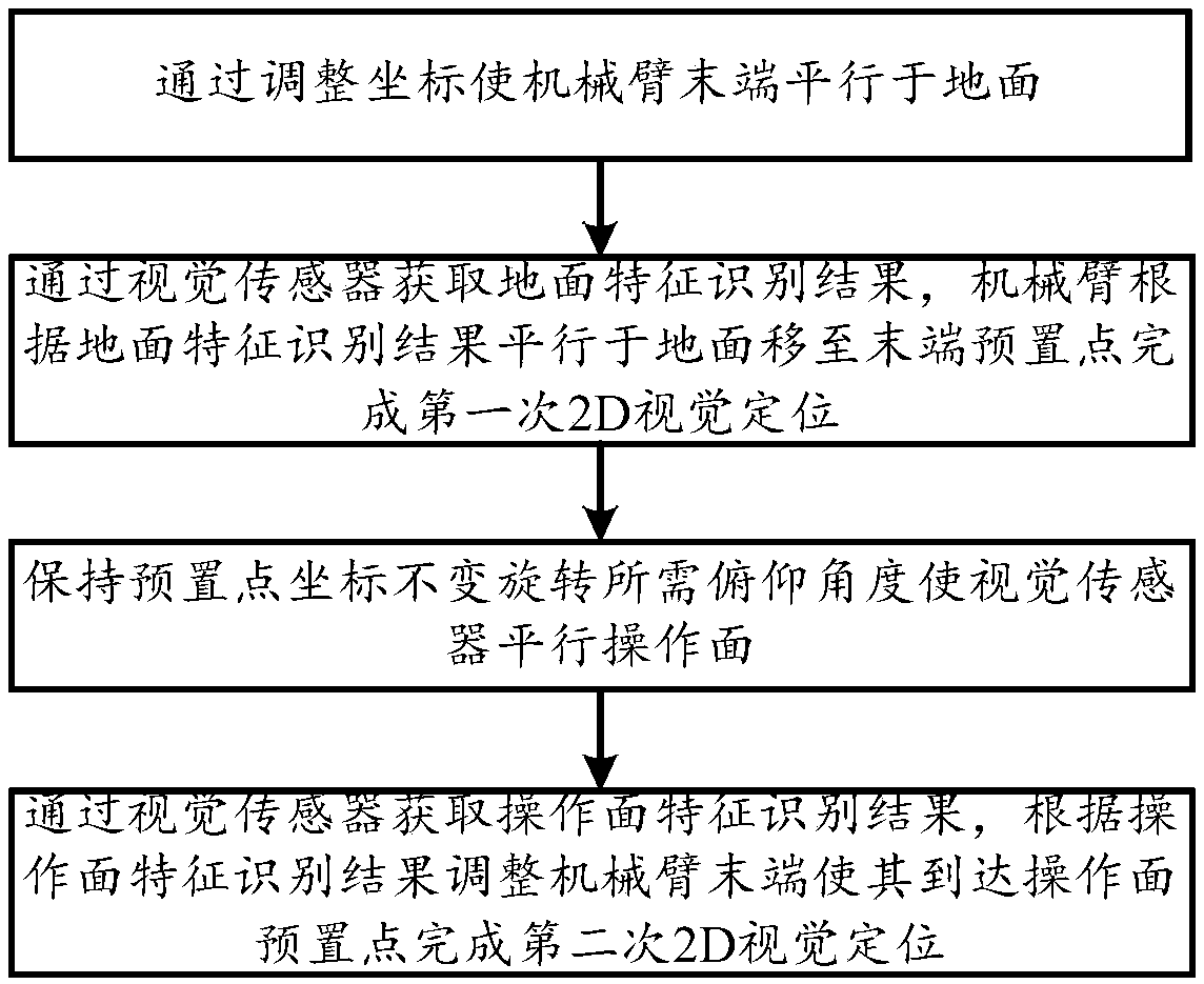
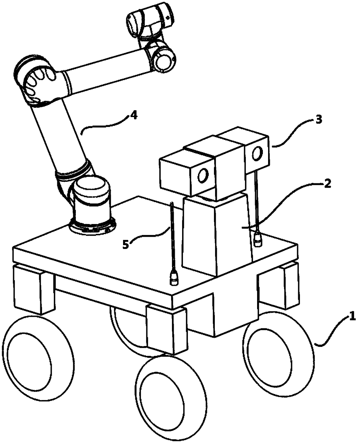
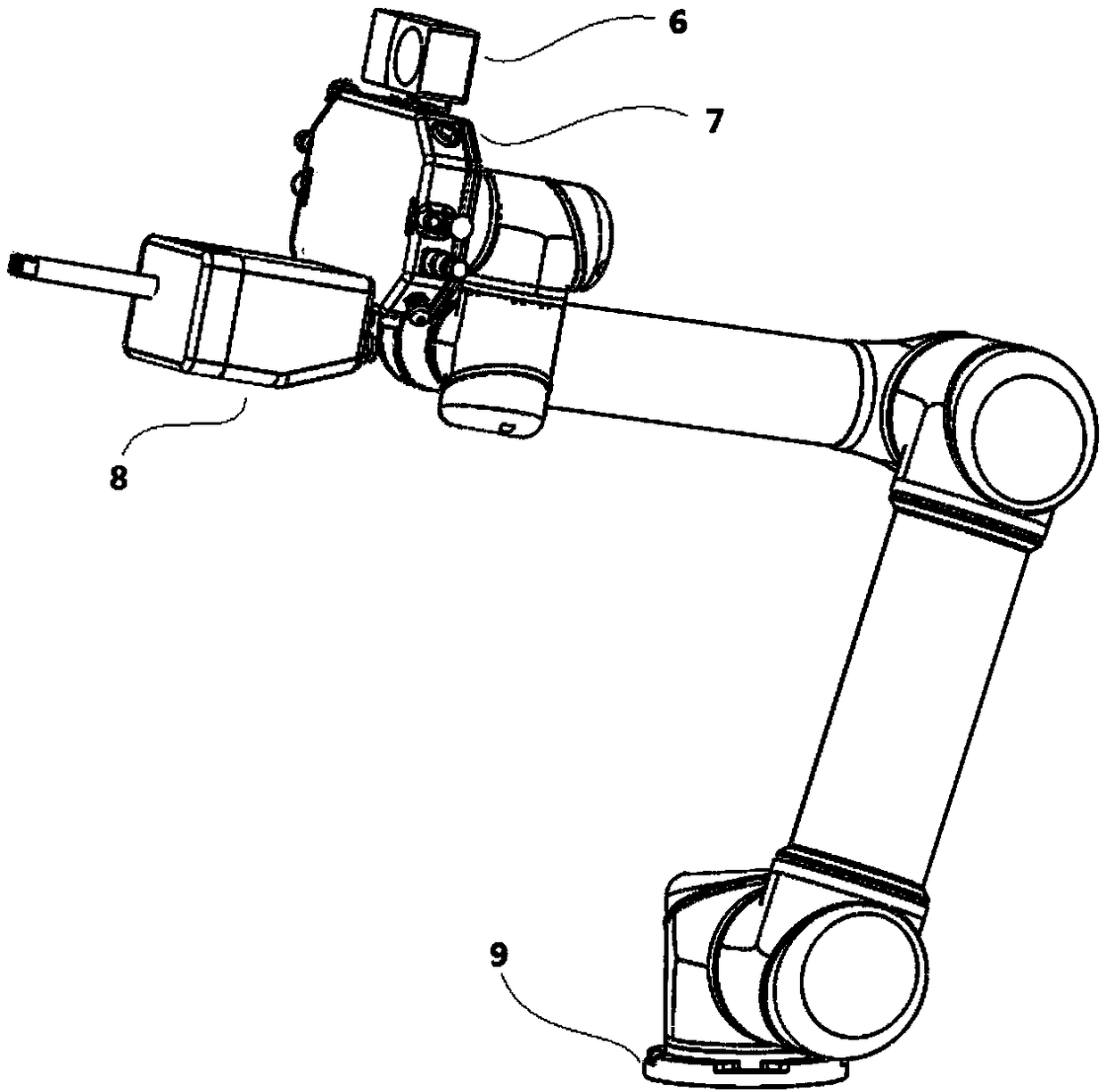
[0045] The inspection robot needs to open the switchgear 11. The inspection robot uses lidar to navigate to the vicinity of the operated equipment. Due to navigation accuracy and motion control accuracy, there is a deviation between the actual position and the preset position. First, adjust the end joint of the robotic arm to keep the end of the rotation vector along the Y axis that is Ry=0°, and the rotation vector along the X axis that is Rx=90°, so that the vision sensor is parallel to the ground, that is, parallel to the XOY plane; The coordinate system is not Figure 4 As shown, it is necessary to make corresponding adjustments according to the settings of the coordinates to make them parallel to the ground after adjustment; then, the vision sensor recognizes the ground features 10 entered into the system in advance; adjusts the position of the robotic arm according to the visual recognition results, in the XOY plane When moving, the height of the end of t...

Example Embodiment

[0046] Example 2

[0047] Based on Example 1, if the operating surface is on the right side of the robot, select the pitch angle of 270 degrees and make the end vision sensor rotate 270 degrees clockwise and then parallel the operating surface; or select the tilt angle of 90 degrees and rotate the end vision sensor 90 degrees counterclockwise. Parallel operation surface. Different angles are selected for positioning according to the position of the operating surface and the robotic arm, to avoid errors caused by position differences, and further improve the spatial positioning accuracy of the end of the robotic arm.


PUM


Abstract

The invention discloses a patrolling robot mechanical arm tail end space positioning method, and belongs to the field of the patrolling robot mechanical arm tail end space positioning method. The method comprises the steps that firstly, the tail end of a mechanical arm is parallel to the ground through adjustment of coordinates; secondly, a vision sensor is used for obtaining the ground feature recognition result, the mechanical arm is parallel to the ground to move to the tail end preset point according to the ground feature recognition result, and first-time 2D vision positioning is finished; thirdly, preset point coordinates are kept unchangeable, the needed pitching angle is rotated, and the vision sensor is made to be parallel to the operation face; and fourthly, the vision sensor isused for obtaining the operation face feature recognition result, the tail end of the mechanical arm is adjusted according to the operation face feature recognition result and is made to arrive at theoperation face preset point, and second-time 2D vision positioning is finished. On the basis of the plane, two-time 2D vision positioning and adjustment are conducted, and the defects that due to adoption of one-time 2D vision positioning, precision is low, and cost is high due to adoption of combination of 2D vision and a distance sensor are overcome; and the positioning cost is reduced, and accurate space positioning is achieved.

Description

technical field [0001] The invention belongs to the field of positioning methods for the end of the manipulator of the inspection robot, in particular to a method for spatially locating the end of the manipulator of the inspection robot. Background technique [0002] In recent years, with the development of the robot industry, security inspection robots have emerged in various fields such as large factories, workshops, and substations. The emergence of inspection robot systems has saved a lot of manpower, material and financial resources, especially for inspections in high-risk places. , the inspection robot becomes the best solution. At present, the inspection robot system has been able to identify various instruments, fire warning and other tasks. In addition, after the inspection robot is equipped with a mechanical arm, it can perform various operations on the site. [0003] At present, the positioning accuracy of most inspection robots based on lidar SLAM navigation is...

Claims


Application Information

Patent Timeline
IPC IPC(8): B25J9/16
CPCB25J9/1697
Inventor 马力赵灿辉王致李骞徐肖庆
Owner YUNNAN POWER GRID CO LTD KUNMING POWER SUPPLY BUREAU
Why Eureka
Try Eureka