Gluing device and gluing method for plate combined machining

A technology of composite processing and gluing device, which is applied in wood processing appliances, adhesive application devices, glue guns, etc., and can solve problems such as gluing dead corners and composite problems.

Active Publication Date: 2018-11-30
挪亚家家具(广东)有限公司
View PDF5 Cites 3 Cited by
  • Summary
  • Abstract
  • Description
  • Claims
  • Application Information

AI Technical Summary

Problems solved by technology

[0003] The more common ones are solid wood composite boards, that is, the boards of different materials are bonded together with glue. In the existing production process, glue is generally applied on the boards manually. This method can also be adapted to boards with small length and width. , but during production, large-sized raw material boards are often used. At this time, manual gluing is applied directly, and there is a dead angle of gluing, which leads to problems in subsequent compounding.

Method used


Image

  • Gluing device and gluing method for plate combined machining
  • Gluing device and gluing method for plate combined machining
  • Gluing device and gluing method for plate combined machining

Examples


Embodiment 1

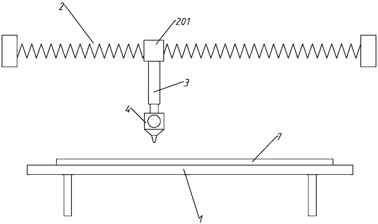
[0032] A gluing device for plate composite processing, comprising a container table 1, a linear module 2, a positioning cylinder 3, and a gluing component 4; the linear module 2 is arranged above the container table 1, and the container table 1 is to be placed Glue-coated plate 7; the movement direction of the sliding table 201 of the linear module 2 is parallel to the length of the plate to be coated 7, and the movement path of the sliding table 201 is greater than the length of the plate to be coated 7; the sliding table 201 of the linear module 2 is directed A position adjustment cylinder 3 is connected below, and the telescopic end of the position adjustment cylinder 3 extends downward and is connected to the glue application assembly 4.

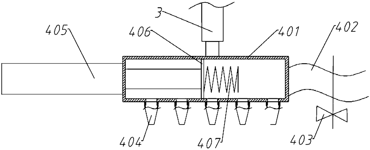
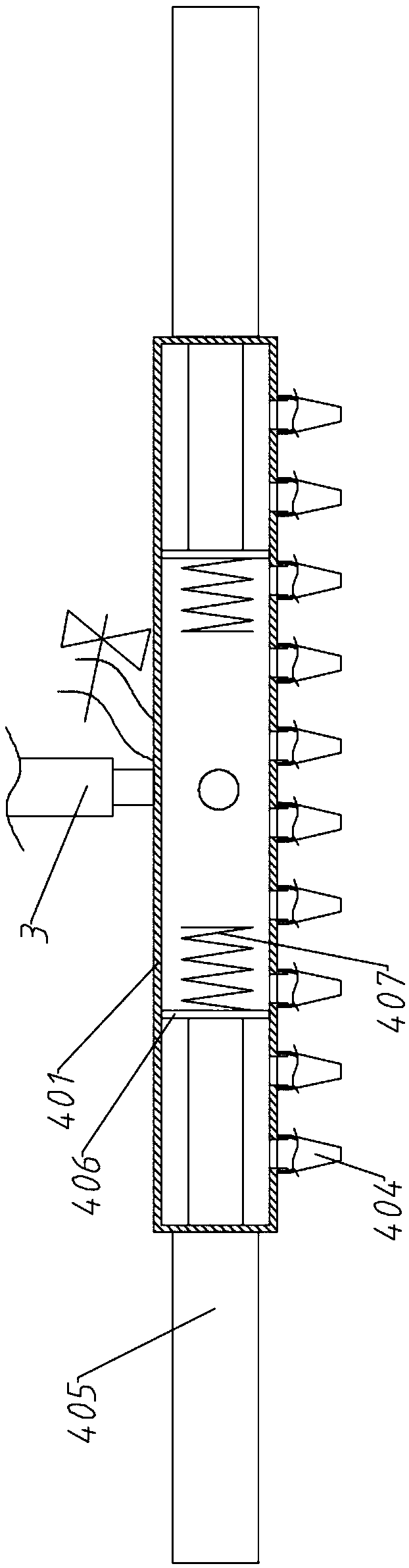
[0033] The gluing assembly 4 includes a cylinder 401, a pitch-adjusting cylinder 405, a piston plate 406, and a glue nozzle 404. The length of the cylinder 401 is greater than the width of the plate 7 to be glued. The cylinder 401 is paralle...

Embodiment 2

[0035] The difference from Embodiment 1 is that the glue application assembly 4 includes a cylinder 401, a pitch-adjusting cylinder 405, a piston plate 406, and a glue nozzle 404. The cylinder 401 is parallel to the width direction of the plate to be coated 7 and the length of the cylinder 401 It is larger than the width of the plate to be coated 7; both ends of the cylinder 401 are provided with a pitch cylinder 405, and the telescopic end of the pitch cylinder 405 extends into the cylinder 401 and is connected with a piston plate 406. The piston plate 406 is provided with spring heating Ring 407, the bottom end of the cylinder 401 is evenly screwed with a glue nozzle 404; the middle section of the cylinder 401 is connected to the glue bucket through a glue pipe 402, and the glue pipe 402 is equipped with a glue valve 403.

[0036] The double-ended setting of the pitch-adjusting cylinder 405 is adopted, which makes the adjustment interval more flexible.

Embodiment 3

[0038] The difference from Embodiment 1 or 2 is that it also includes a controller, the linear module 2, the position adjusting cylinder 3, the pitch adjusting cylinder 405, the spring heating coil 407, and the glue inlet valve 403 are respectively connected to the controller.

[0039] The controller model is Texas Instruments MSP430, and the linear module 2 uses silver KK100. Since the technical effect achieved by embodiment 3 is the most, this embodiment is used for explanation, that is, the glue application method of this device:

[0040] S1: Place the plate 7 to be glued on the holding table 1, and keep the length direction of the plate parallel to the movement path of the linear module sliding table 201;

[0041] S2, according to the position, length and width of the plate 7 to be coated, adjust the effective spray interval of the glue application assembly 4, and adjust the effective spray interval of the glue application assembly 4;

[0042] Control the distance adjustment cylind...


PUM


Abstract

The invention relates to the technical field of plate combined machining and specifically relates to a gluing device and a gluing method for plate combined machining. The device comprises a placementtable, a linear module, a positioning air cylinder and a gluing component. Through mechanical design, the linear module serves as a spraying path, the spraying interval and spraying distance are adjusted according to the parameters such as length and width of the plate, and then the gluing plate is glued along a single direction; during batch production machining of large-size plates, compared with direct manual gluing, the dead angle in gluing is effectively reduced, and the efficiency is remarkably improved.

Description

Technical field [0001] The invention relates to the technical field of plate composite processing, in particular to a gluing device and a gluing method for plate composite processing. Background technique [0002] Composite board refers to a board composed of two or more materials, [0003] The more common one is the solid wood composite board, that is, the boards of different materials are glued together with glue. In the existing production process, the boards are usually glued manually. This method can also be adapted to the boards with small length and width. However, in production, large-sized raw boards are often used. At this time, the glue is applied directly by hand, and there is a dead corner of glue, which causes problems in subsequent lamination. Summary of the invention [0004] (1) Technical problems solved [0005] The purpose of the present invention is to overcome the shortcomings of the prior art, and provide a gluing device and a gluing method for sheet composite ...

Claims


Application Information

Patent Timeline
Patent Type & Authority Applications(China)
IPC IPC(8): B27G11/00
CPCB27G11/005
Inventor 段涛
Owner 挪亚家家具(广东)有限公司
Why Eureka
Try Eureka