
Automatic bonding equipment for rubber strip

An automatic bonding and rubber strip technology, which is applied in the field of automatic robotic arms, can solve the problems of difficulty in ensuring efficiency and the dependence of bonding yield on manual proficiency, so as to ensure product uniformity, improve operating process efficiency, and gripping accuracy high effect

Pending Publication Date: 2018-11-30
WUXI JONES TECH +1
View PDF0 Cites 0 Cited by
  • Summary
  • Abstract
  • Description
  • Claims
  • Application Information

AI Technical Summary

Problems solved by technology

[0002] In the field of rubber, due to the bonding requirements of rubber strips, most of the existing processes use manual and tooling to bond rubber rings. The bonding yield depends on manual proficiency, and the efficiency is difficult to guarantee.

Method used


Image

  • Automatic bonding equipment for rubber strip
  • Automatic bonding equipment for rubber strip
  • Automatic bonding equipment for rubber strip

Examples


Embodiment Construction

[0026] The present invention will be further described below in conjunction with specific drawings and embodiments.

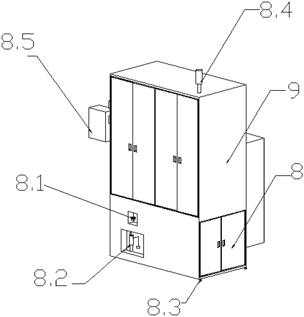
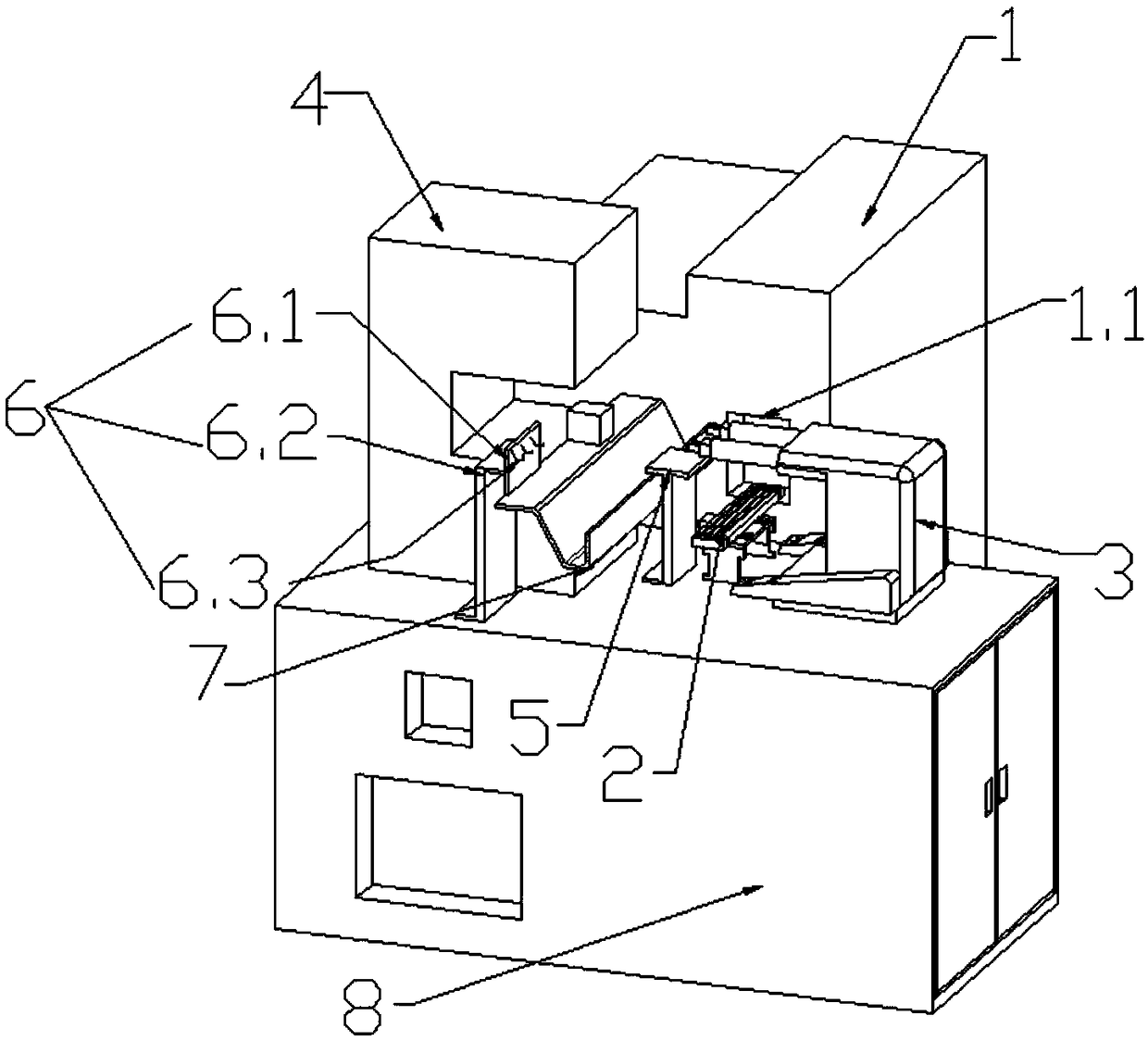
[0027] Such as Figure 1-5 Shown: The equipment is fully enclosed to ensure personal safety; when material needs to be taken, the door can be opened to take material (the equipment stops running when the door is opened).

[0028] A rubber strip automatic bonding equipment is characterized in that it includes a control seat 8 and an operation cabinet 9;

[0029] The control seat 8 is arranged at the bottom of the operation cabinet 9;

[0030] Adhesive strip bonding parts are arranged in the operation cabinet, and a drive control device is arranged in the control seat;

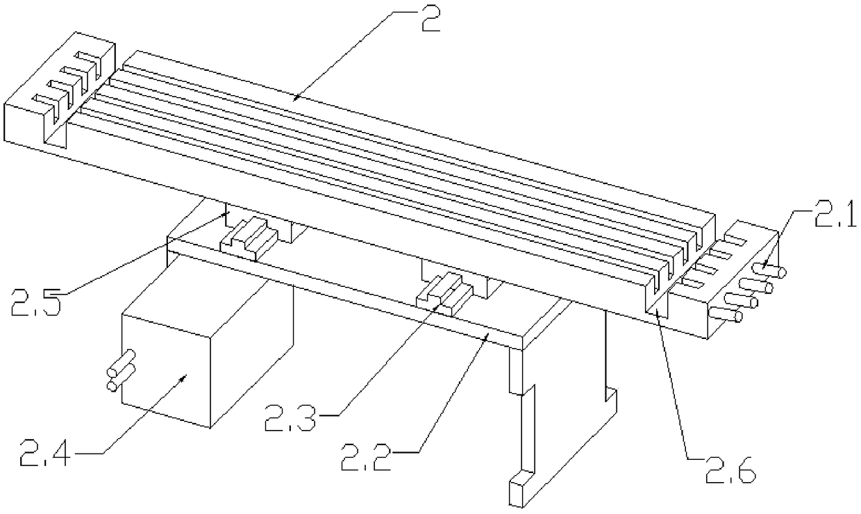
[0031] The glue strip bonding parts include glue strip cutting equipment 1, glue strip positioning groove plate 2, mechanical arm assembly 3, glue strip hot pressing equipment 4, glue platform 5, wire hanger 6 and wire support tray 7;

[0032] The rubber strip hot-pressing equipment 4 includes...


PUM


Abstract

The invention relates to automatic bonding equipment for a rubber strip. The automatic bonding equipment comprises a control base and an operation cabinet, wherein the control base is arranged at thebottom of the operation cabinet; a rubber strip bonding assembly is arranged in the operation cabinet; a drive control device is arranged in the control base; the rubber strip bonding assembly comprises rubber strip cutting equipment, a rubber strip positioning groove plate, a mechanical arm component, rubber strip hot pressing equipment, an adhesive platform, a wire hanging frame and a wire supporting plate; the rubber strip hot pressing equipment comprises a press fit head and a press fit platform, and a pressure welding jig is arranged under the press fit head and located in the center of the press fit platform; the wire supporting plate is arranged on the upper surface of the press fit platform and comprises a platform and a bearing trough, and the bearing trough has a slope structure;workpieces hung on hooks falls on the slope structure of the bearing trough accordingly and are borne by the bottom of the bearing trough; a hole accommodating extension of the pressure welding jig is formed in the platform; and the adhesive platform is located between the wire supporting plate and the mechanical arm component. An automatic machine is utilized to replace manual work, the efficiency is improved, and the yield stability is improved.

Description

technical field [0001] The invention relates to an automatic mechanical arm, which is used in the process of sticking rubber rings, in particular, automatic machinery is used to replace manual automatic bonding equipment for rubber strips. Background technique [0002] In the field of rubber, due to the bonding requirements of rubber strips, most of the existing processes use manual tooling to bond rubber rings. The bonding yield depends on manual proficiency, and the efficiency is difficult to guarantee. Contents of the invention [0003] The purpose of the present invention is to use machinery to replace labor, improve efficiency, and ensure a stable product yield. A rubber strip automatic bonding equipment is characterized in that it includes a control seat and an operation cabinet; [0004] The control seat is arranged at the bottom of the operation cabinet; [0005] Adhesive strip bonding parts are arranged in the operation cabinet, and a drive control device is arra...

Claims


Application Information

Patent Timeline
Patent Type & Authority Applications(China)
IPC IPC(8): B29C65/48B29C65/74B29C65/78
CPCB29C65/48B29C65/741B29C65/7841B29C66/1142
Inventor 陈曲李易罡朱光福申永强
Owner WUXI JONES TECH
Learn More