
Electric bicycle foot stand electronic lock

An electric vehicle and electronic lock technology, which is applied to bicycle accessories, bicycle brackets, bicycle brakes, etc., can solve the problems of affecting the stability of the electric vehicle, poor stability of the electric vehicle, and easy rolling of the wheels, so as to prevent the vehicle body Effects of tilting, diversification of functions, and movement prevention of the vehicle body

Active Publication Date: 2018-11-30
HUNAN INST OF TECH
View PDF5 Cites 2 Cited by
  • Summary
  • Abstract
  • Description
  • Claims
  • Application Information

AI Technical Summary

Problems solved by technology

The traditional electric vehicle foot support is lifted or lowered by being tensioned by a spring and rotating around a point. This type of electric vehicle foot support has a significant defect. The stability of it supporting the electric vehicle is not good. The reason is The reason is: when the electric vehicle is parked, its wheels are not completely braked. In many cases, the wheels are prone to rolling. At this time, the spring on the foot support cannot tighten the foot support well, so the foot support will follow The rolling of the wheels moves to the left or backward, which affects the stability of the supporting electric vehicle
In addition, the traditional electric vehicle foot support only has the function of supporting the electric vehicle, and its function is relatively single.

Method used


Image

  • Electric bicycle foot stand electronic lock
  • Electric bicycle foot stand electronic lock
  • Electric bicycle foot stand electronic lock

Examples


Embodiment Construction

[0026] In order to facilitate the understanding of those skilled in the art, the present invention will be further described below in conjunction with the embodiments and accompanying drawings, and the contents mentioned in the embodiments are not intended to limit the present invention.

[0027] In describing the present invention, it is to be understood that the terms "upper", "lower", "front", "rear", "left", "right", "vertical", "horizontal", "top", The orientation or positional relationship indicated by "bottom", "inner", "outer", etc. is based on the orientation or positional relationship shown in the drawings, and is only for the convenience of describing the present invention and simplifying the description, rather than indicating or implying the referred device Or elements must have a certain orientation, be constructed and operate in a certain orientation, and thus should not be construed as limiting the invention.

[0028] In the description of the present invention...


PUM


Abstract

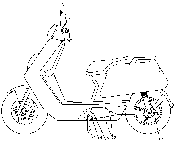
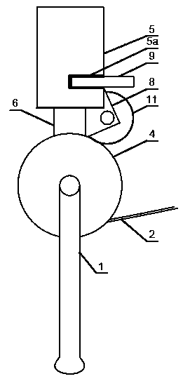
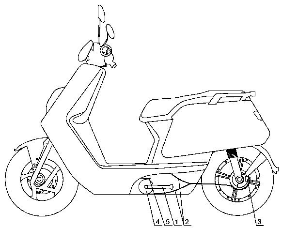
The invention provides an electric bicycle foot stand electronic lock and relates to the technical field of electric bicycles. The electric bicycle foot stand electronic lock comprises a foot stand, abrake cable, a disc brake, a lock disc, a guide barrel, a lock bolt, a spring vertically arranged in the guide barrel, a sector gear, a locking board, a round gear, a motor and a control chip. The middle portion of the lock disc is vertically connected with a rotary shaft of the round gear, a cable groove is formed in the edge of the lock disc for a circle, one end of the brake cable is fixed into the cable groove, the other end of the brake cable extends out from the lower end of the lock disc along the cable groove and is connected with the disc brake, a lock bolt groove with an arc-shapedtransverse section is formed in the cable groove, an arc-shaped structure matched with the lock bolt groove is formed in the bottom of the lock bolt, a notch communicating with the inner portion and the outer portion is formed in the barrel wall of the guide barrel, the front end of the locking board is inserted in the notch, and a row of tooth grooves matched with the sector gear are formed in the bottom face of the locking board. The electric bicycle foot stand electronic lock has electric bicycle supporting and locking functions, electric bicycle supporting stability can be effectively improved, and an antitheft effect can be achieved.

Description

technical field [0001] The invention relates to the technical field of electric vehicles, in particular to an electric vehicle pedal electronic lock. Background technique [0002] The electric vehicle foot support is a strut structure used to support the electric vehicle to prevent the electric vehicle from tipping over. When the electric vehicle is used, the foot support is lifted and placed next to the vehicle body. When the electric vehicle is parked, the foot support is lowered to support the ground . The traditional electric vehicle foot support is lifted or lowered by being tensioned by a spring and rotating around a point. This type of electric vehicle foot support has a significant defect. The stability of it supporting the electric vehicle is not good. The reason is The reason is: when the electric vehicle is parked, its wheels are not completely braked. In many cases, the wheels are prone to rolling. At this time, the spring on the foot support cannot tighten the ...

Claims


Application Information

Patent Timeline
Patent Type & Authority Applications(China)
IPC IPC(8): B62H1/02B62H5/18B62L3/04
CPCB62H1/02B62H5/18B62L3/04
Inventor 颜军张译之周宇辰唐红罗前进胡凌雪
Owner HUNAN INST OF TECH
Learn More