
A steel structure frame of a loading station integrated with a warehouse body and a supporting structure

A supporting structure and loading station technology, which is applied in the directions of transportation, packaging, loading/unloading, etc., can solve the problems of increasing the cross-section of columns and beams, and increasing the cost of structural frames, so as to reduce steel consumption, improve reliability, and enhance bearing capacity effect of ability

Active Publication Date: 2020-07-24
中煤科工智能储装技术有限公司 +1
View PDF5 Cites 0 Cited by
  • Summary
  • Abstract
  • Description
  • Claims
  • Application Information

AI Technical Summary

Problems solved by technology

Such a traditional support structure reveals obvious defects: both columns and beams must be very strong, that is, the cross-section of columns and beams increases significantly
The strong structure and weight make the cost of the structural frame rise rapidly, and become the main cost in the cost structure of the entire equipment

Method used


Image

  • A steel structure frame of a loading station integrated with a warehouse body and a supporting structure
  • A steel structure frame of a loading station integrated with a warehouse body and a supporting structure
  • A steel structure frame of a loading station integrated with a warehouse body and a supporting structure

Examples


Embodiment 1

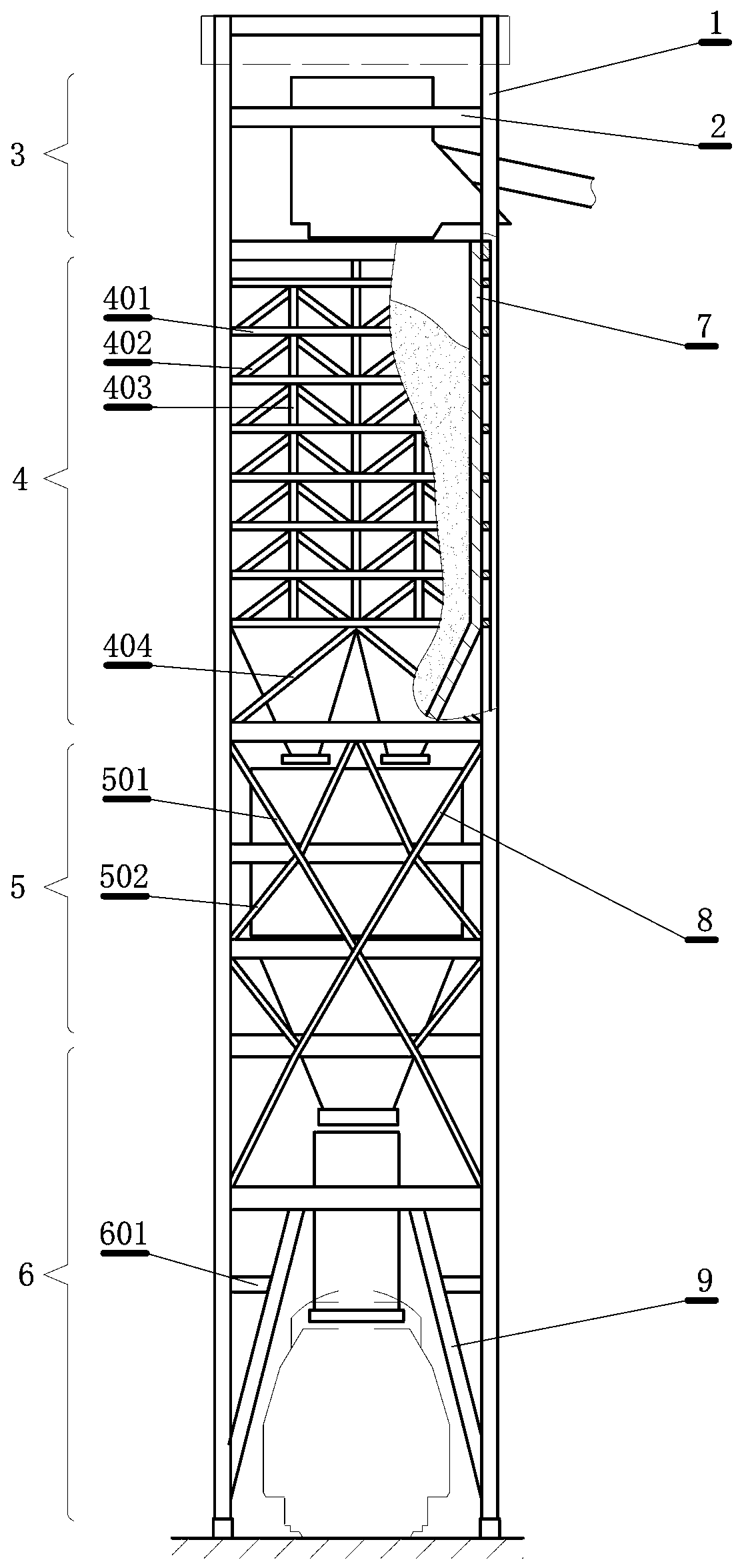
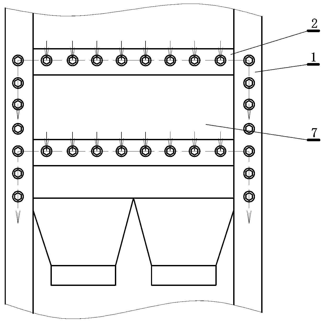
[0020] This embodiment is a steel structure frame of a loading station in which the warehouse body and the support structure are integrated, such as figure 1 shown. This embodiment includes: at least four vertical columns 1, and beams 2 connecting the columns are arranged between the columns. The columns and beams form a basic structure, and the basic structure is divided into Belt conveyor head layer 3, buffer bin layer 4, quantitative bin layer 5, chute and vehicle layer 6, the columns and beams of the buffer bin layer are connected to the side plates 7 of the buffer bin through densely arranged connectors or welding, A fork-shaped truss 8 is arranged on the quantitative warehouse layer, and a slanted pillar 9 is arranged on the chute and the vehicle layer.

[0021] The basic idea of ​​this embodiment is to integrate the buffer warehouse with the largest load capacity (generally carrying nearly 100 tons or more of bulk cargo) with the rigid structure frame, and use the side...

Embodiment 2

[0043] This embodiment is an improvement of the first embodiment, and is a refinement of the first embodiment on the buffer layer. At least two groups of herringbone inclined beams 402 are set up side by side between the buffer storey beams 401 described in this embodiment, and short columns 403 are arranged in the middle and both sides of the said herringbone inclined beams, such as figure 1 shown.

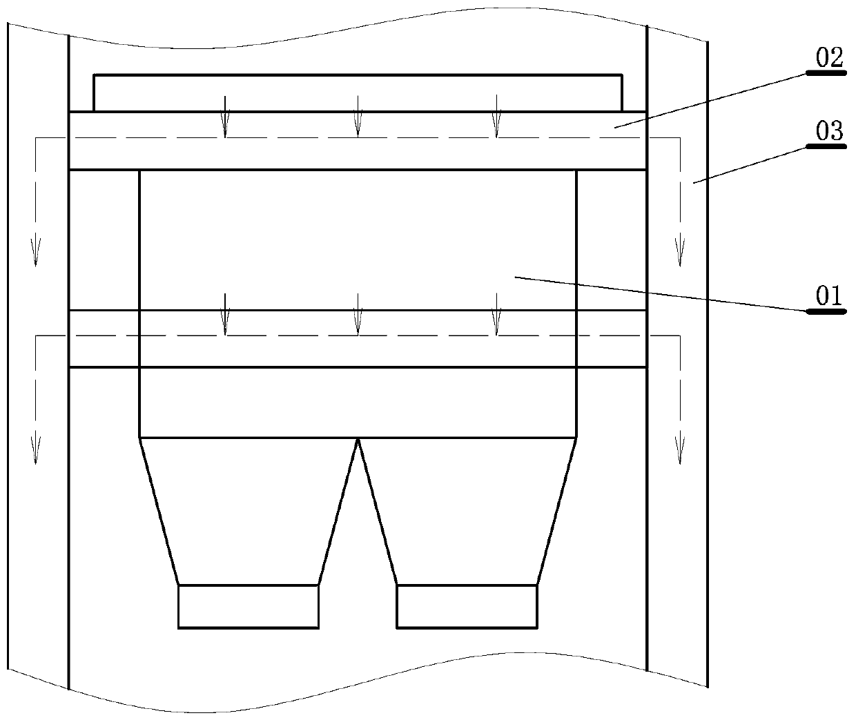
[0044] In order to maintain the stability of the buffer silo slab, set beams on the slab and use welding to connect them, or use connectors, that is, high-strength bolts to firmly connect each beam to the slab. Herringbone inclined beams are used between the beams, and small columns are arranged between the inclined beams. Through the herringbone inclined beam and the small column, the stress on the warehouse plate is transferred to the column, and at the same time, the instability of the plate surface caused by the lateral force is avoided.

Embodiment 3

[0046] This embodiment is an improvement of the above embodiment, and is a refinement of the above embodiment regarding the buffer storey layer. The lowermost beam of the buffer warehouse layer described in this embodiment is provided with a large herringbone beam 404 connected to the column, such as figure 1 shown.

[0047] The center of the large herringbone inclined beam is supported at the center of the bottom beam of the buffer storey, that is, the position with the largest winding, to ensure the stability of the beams of each buffer store.


PUM


Abstract

The invention relates to a bin body and support structure fused loading station steel structured frame. The frame comprises stand columns, and a cross beam between the stand columns; the stand columnsand the cross beam form a basic structure; a belt conveyor head layer, a buffer bin layer, a quantitative bin layer, a chute and a vehicle layer are divided in the basic structure in sequence from top to bottom; the stand columns and the cross beam of the buffer bin layer are connected to side plates of a buffer bin through connecting pieces densely arranged, or are welded with the same; the quantitative bin layer is provided with a fork-shaped truss; and the chute and the vehicle layer are provided with inclined support columns. Bin plates of the buffer bin are directly mounted on the steelstructured frame; and the buffer bin and the steel structured frame are fused to form a steel frame buffer bin rigid body, so that the bearing capacity of the buffer bin is improved, and the bearing capacity and the side wind resistance of the steel structured frame are improved. The quantitative bin layer is skillfully combined with such stress modes as a deep beam and the truss; and in particular, the stress mechanisms of two force rods are exerted to the greatest extent, so that the pulling and pressing characteristics of rod pieces are fully exerted, the steel consumption is reduced, and the structure reliability is improved.

Description

technical field [0001] The invention relates to a steel structure frame of a loading station integrated with a warehouse body and a supporting structure, is a transport machine, and is a supporting structure for an automatic loading station of bulk goods. Background technique [0002] The bulk cargo automatic loading station is composed of a steel structure frame, a buffer warehouse, a quantitative warehouse and a chute. Among them, the steel structure frame is the supporting structure, which bears the weight of all other components and the transported materials. Since the steel frame is a slender and tall structure, its aspect ratio is greater than 3. Therefore, the structure of the steel frame should not only consider the bearing weight, but also consider the change of internal alternating stress, the influence of crosswind, and the earthquake force. Issues with external belt tension, bridge lap loads and buckling. [0003] The traditional steel structure frame of the lo...

Claims


Application Information

Patent Timeline
Patent Type & Authority Patents(China)
IPC IPC(8): B65G67/06B65G67/08
CPCB65G67/06B65G67/08
Inventor 常杰云张新孙国顺张绪帅张兆杰袁华李旭
Owner 中煤科工智能储装技术有限公司
Learn More