Full-automatic welding wire layer winding machine

A layer winding machine, fully automatic technology, applied in the direction of conveying filament materials, thin material processing, transportation and packaging, etc., can solve the problems of high labor intensity, low work efficiency, low automation level of welding wire layer winding machine, etc., to achieve The effect of reducing production costs and improving work efficiency

Pending Publication Date: 2018-11-30
JIANGNAN UNIV
View PDF27 Cites 11 Cited by
  • Summary
  • Abstract
  • Description
  • Claims
  • Application Information

AI Technical Summary

Problems solved by technology

[0003] The automation level of the current welding wire layer winding machine is not high, the main reason is that it fails to solve three key problems: first, at the beginning, the beginning of the welding wire is automatically bent into a hook shape and hooked onto the wire reel, which is called "hooking". The second is that during the layer winding process, it is automatically ensured that each layer of welding wire is closely arranged with the welding wire of the adjacent circle when winding, and there is no gap or overlap, which is called "tight layer winding"; the third is that in the layer At the end of winding, the welding wire is automatically cut off, and the end of the welding wire is passed into the corresponding hole on the welding wire reel and automatically bent, which is called "final hook wire".
Due to the failure to solve these three key problems, the existing welding wire layer winding machine needs to manually complete a large number of repeated operations, which has high labor intensity, low work efficiency and high production cost.

Method used


Image

  • Full-automatic welding wire layer winding machine
  • Full-automatic welding wire layer winding machine
  • Full-automatic welding wire layer winding machine

Examples


Embodiment Construction

[0039] The method of the invention will be further described below in conjunction with the accompanying drawings and examples.

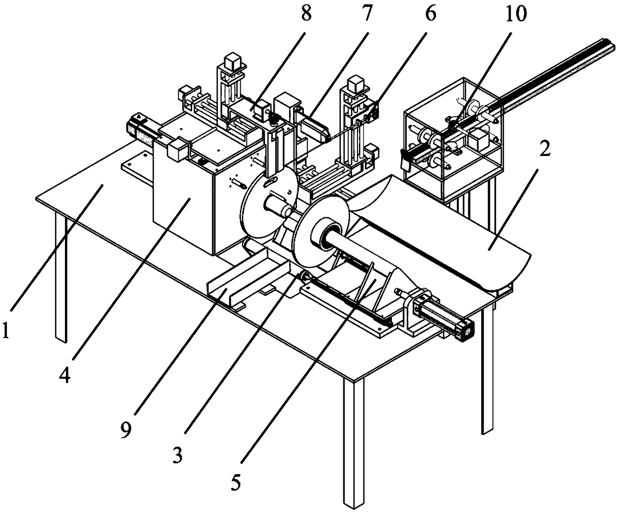
[0040] In order to describe the relative position of each part and the moving direction of each moving part more clearly, three directions X, Y, and Z are defined to construct a rectangular coordinate system, where the X direction indicates the direction along the axis of the main shaft to the tailstock, and the Y direction indicates Parallel to the plane of the workbench, perpendicular to the X direction and pointing to the side of the wire reel discharge slot, and the Z direction is perpendicular to the plane of the workbench and facing upwards.

[0041] A kind of fully automatic welding wire layer winding machine proposed by the present invention, a kind of implementation example thereof is figure 1 As shown, in this example, the wire reel feeding chute 2, the main shaft part 4, the tailstock part 5, the wire feeding part 6, and the wire reel outl...


PUM


Abstract

The invention discloses a full-automatic welding wire layer winding machine. The full-automatic welding wire layer winding machine comprises a workbench and further comprises a welding wire disc feeding groove, a lifting part, a main shaft part, a tail base part, a wire feeding part and a welding wire disc discharging groove, all of which are formed in the workbench. The main shaft part is provided with a wire shearing part and a wire folding and inserting part. A moving part arranged on one side of the workbench is further included. The full-automatic welding wire layer winding machine can solve the three key technology problems about automatic hook wire rising, tight layer winding and hook wire terminating, accordingly the welding wire layer winding process is fully automatic, manual operation is not needed in the whole process, and the whole process is automatically finished through the machine. The work efficiency can be greatly improved, and the production cost is reduced.

Description

technical field [0001] The invention relates to a fully automatic welding wire layer winding machine, which belongs to the technical field of automatic industrial equipment. Background technique [0002] Welding wire layer winding machine is a kind of equipment that regularly winds the processed finished welding wire layer by layer on the welding wire reel for packaging, storage, circulation and sales. The welding wire obtained through welding wire layer winding is several kilograms per reel To tens of kilograms, easy to circulate and use, it is the last process of welding wire production. The welding wire layer winding process is generally divided into the following steps. First, the starting end of the welding wire needs to be bent to form a hook shape, hook it to the gap on the wire reel, and then turn the wire reel to wind the welding wire onto the wire reel. Each layer The welding wire rings are closely arranged between the rings, and the next layer is wound after one ...

Claims


Application Information

Patent Timeline
Patent Type & Authority Applications(China)
IPC IPC(8): B65H67/06B65H54/553B65H54/22B65H65/00
CPCB65H54/22B65H54/553B65H65/00B65H65/005B65H67/06B65H2701/36
Inventor 徐杰
Owner JIANGNAN UNIV
Why Eureka
Try Eureka