Feeding apparatus for embroidery machine

The technology of a feeding device and an embroidery machine is applied in the field of embroidery equipment, which can solve the problems of increasing the input of manpower and reducing the production efficiency of the embroidery machine, and achieve the effects of improving the production efficiency, facilitating the processing and improving the stability.

Active Publication Date: 2018-11-30
杭州庄氏布业有限公司
View PDF9 Cites 2 Cited by
  • Summary
  • Abstract
  • Description
  • Claims
  • Application Information

AI Technical Summary

Problems solved by technology

[0003] In the production process of the existing embroidery machine, the fabric needs to be manually fixed and tightened. This kind of embroidery machine increases the input of manpower during the use process and reduces the production efficiency of the embroidery machine.

Method used


Image

  • Feeding apparatus for embroidery machine
  • Feeding apparatus for embroidery machine
  • Feeding apparatus for embroidery machine

Examples


Embodiment Construction

[0029] The present invention will be further described with reference to the accompanying drawings.

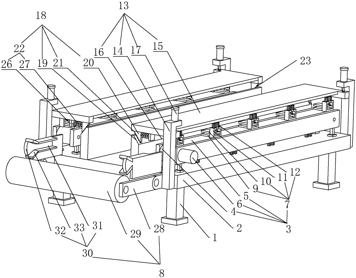
[0030] A kind of embroidery machine feeding device, such as figure 1 As shown, a bracket 1 is included, a workbench 2 is fixedly connected to the bracket 1, a feed mechanism 3 for convenient feeding is provided on the workbench 2, and a feed assembly 8 for convenient feeding is provided on one end of the workbench 2 .

[0031] Such as figure 1 As shown, a feeding mechanism 3 for convenient feeding is provided on the workbench 2. The feeding mechanism 3 includes a rotating wheel 4, a conveyor belt 5, a driving motor 6, and a clamping mechanism 7. Two groups of rotating wheels 4 are connected in rotation respectively. On both ends of the worktable 2; the conveyor belt 5 is wound on two sets of rotating wheels 4; the driving motor 6 is fixedly connected to one end of the working table 2, and the output shaft of the driving motor 6 is fixedly connected to the axis of the rotatin...


PUM


Abstract

The invention relates to embroidery equipment, specifically to a feeding apparatus for an embroidery machine. The feeding apparatus comprises a bracket and a worktable arranged on and fixedly connected with the bracket, wherein a feeding mechanism convenient for feeding is mounted on the worktable; the feeding mechanism comprises rotating wheels rotatably connected with both ends of the worktable,a conveyor belt wound between two groups of the rotating wheels, a driving motor arranged on and fixedly connected with the worktable, and a plurality of groups of clamping mechanisms arranged on thesurface of the conveyor belt; the output shaft of the driving motor is fixedly connected with the rotating wheels; and a feeding assembly convenient for feeding is arranged on one end of the worktable. A fabric is clamped by the clamping mechanisms; the driving motor drives the rotating wheel to rotate; the rotating wheels drive the fabric to move through the conveyor belt; and thus, the step ofmanual fixing of the fabric is omitted. Since the fabric is fixed by a mechanical structure instead of human beings, the production efficiency of the embroidery machine is improved.

Description

technical field [0001] The invention relates to an embroidery device, in particular to an embroidery machine feeding device. Background technique [0002] Embroidery machine, literally, I think everyone should understand, embroidery machine, embroidery machine, or embroidery machine. When embroidery just started to break away from manual embroidery, the so-called embroidery machine at that time was not a real embroidery machine, because the embroidery machine at that time used a traditional sewing machine, replaced with a bottom plate with a small round hole, and the sewing machine needle kept going. Going in and out up and down, plus moving the cloth taut with the embroidery frame back and forth, in fact, this so-called embroidery machine is still a kind of hand embroidery. [0003] In the production process of the existing embroidery machine, the fabric needs to be fixed and tightened manually, which increases the input of manpower during the use of the embroidery machine...

Claims


Application Information

Patent Timeline
Patent Type & Authority Applications(China)
IPC IPC(8): D05C9/06
CPCD05C9/06D05D2207/02
Inventor 庄静松
Owner 杭州庄氏布业有限公司
Why Eureka
Try Eureka