
An intelligent clamping and fixing device for circuit board welding

A technology for clamping and fixing circuit boards, applied in welding equipment, auxiliary welding equipment, welding/cutting auxiliary equipment, etc., can solve the problems of only considering circuit boards, inconvenient flipping, simple structure, etc., to reduce the number of fixing steps and structures Stabilization and the effect of improving welding efficiency

Inactive Publication Date: 2021-01-26
GUILIN UNIV OF AEROSPACE TECH
View PDF10 Cites 0 Cited by
  • Summary
  • Abstract
  • Description
  • Claims
  • Application Information

AI Technical Summary

Problems solved by technology

[0003] The current existing circuit board fixing equipment is often too simple in structure, only considering the length and width of the circuit board and ignoring its thickness, or when clamping the circuit board, it is often inconvenient to turn over, and the outer layer of the circuit board is divided into upper and lower parts. Layer, when the existing device clamps it, it can only deal with one side. When processing the other side, it needs to be removed and clamped again. For example, the application number is 201611006345.3, and the publication number is the Chinese patent of CN106624536A (A Circuit Board Welding and Fixing Fixture) discloses "a circuit board welding and fixing fixture, including a base and a clamping device, the clamping device is arranged on the base, and it is characterized in that: the clamping device includes a movable assembly and a fixed assembly, the movable assembly includes a guide rail, a slider and a fixed plate, the guide rail is fixedly arranged on the base, the guide rail is provided with the slider, and the slider is connected to the fixed plate, The fixed plate is provided with a movable clamping block, the fixed assembly includes a fixed seat and a fixed clamping block, the fixed seat is fixed on the base, and the fixed seat is provided with the fixed clamping block. piece
", the patent has the above-mentioned problems, when the circuit board is clamped, it is inconvenient to turn over

Method used


Image

  • An intelligent clamping and fixing device for circuit board welding
  • An intelligent clamping and fixing device for circuit board welding
  • An intelligent clamping and fixing device for circuit board welding

Examples


Embodiment

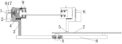
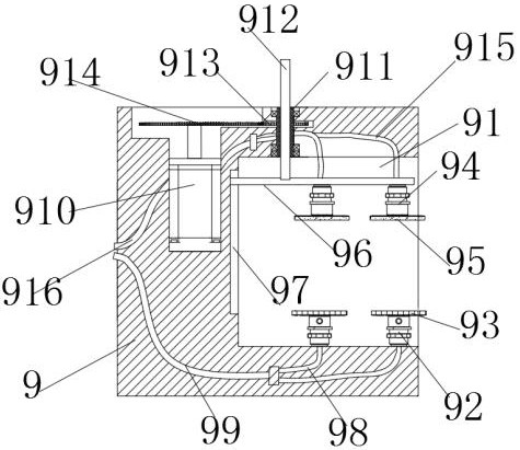
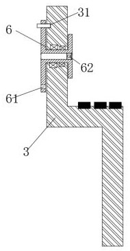
[0024] Example: see Figure 1-5 , the present invention provides a technical solution: an intelligent clamping and fixing device for circuit board welding, which is characterized in that it includes a fixed clamping assembly and a moving clamping assembly, and the fixed clamping assembly includes a clamping seat body 9, Angle adjustment device, base 1 and fixed base 3, the base 1 is fixedly arranged on one side of the fixed base 3, the moving clamping assembly is used to adjust the distance from the fixed clamping assembly and is in common with the fixed clamping assembly Clamping the circuit board; the fixed clamping assembly and the moving clamping assembly both include a fixed adsorption device and a mobile pressure applying device; the angle adjustment device is used to adjust the angle between the circuit board and the horizontal plane;

[0025] Wherein, the fixed clamping assembly is fixed on the installation seat 8 through the fixed seat 3, and the fixed seat 3 is embed...


PUM


Abstract

The invention discloses an intelligent clamping and fixing device for circuit board welding, which is characterized in that it comprises a fixed clamping component, a moving clamping component and an angle adjustment device, and the moving clamping component is used for adjusting and fixing the clamping component distance and clamp the circuit board together with the fixed clamping assembly; the angle adjustment device is used to adjust the angle between the circuit board and the horizontal plane. Adjust the angle between the circuit board and the horizontal plane to meet the needs of inspection boards or welding, and the two turntables are provided with different numbers of indexing holes, and the two turntables can be used together to adjust their angles quickly and efficiently; the invention provides There are movable clamping components to clamp circuit boards of different lengths; in addition, the low-level boards are fixed by suction cups, which reduces many traditional fixing steps and improves welding efficiency.

Description

technical field [0001] The invention belongs to the field of circuit board clamping, and in particular relates to an intelligent clamping and fixing device for circuit board welding. Background technique [0002] Circuit boards are also called PCB boards. PCB boards can be divided into low-order boards and high-order boards according to the number of layers. Low-order boards have fewer layers and are thinner, while high-order boards have more layers and are thicker. Whether it is a low-level board or a high-level board, its size is often not fixed. Therefore, when processing a circuit board, it is necessary to consider both its thickness and its length and width. [0003] The current existing circuit board fixing equipment is often too simple in structure, only considering the length and width of the circuit board and ignoring its thickness, or when clamping the circuit board, it is often inconvenient to turn over, and the outer layer of the circuit board is divided into upp...

Claims


Application Information

Patent Timeline
Patent Type & Authority Patents(China)
IPC IPC(8): B23K3/08B23K37/04B23K37/047B23K101/42
CPCB23K3/087B23K37/047B23K2101/42
Inventor 简远鸣邓莉赵长青陈少航
Owner GUILIN UNIV OF AEROSPACE TECH
Learn More