Rotor device of hydrapulper

A hydraulic pulper and rotor technology, which is used in textile and papermaking, raw material separation, fiber raw material processing, etc., can solve the problems of large power consumption, inability to ensure full circulation of pulp, etc., to achieve convenient operation and maintenance, and improve the disintegration effect. , the effect of reducing power consumption

Pending Publication Date: 2018-11-30
JIANGSU DATANG MACHINERY
View PDF0 Cites 5 Cited by
  • Summary
  • Abstract
  • Description
  • Claims
  • Application Information

AI Technical Summary

Problems solved by technology

When the diameter of the rotor is equivalent to 0.2 to 0.3 times the diameter of the tank body, the crushing effect is good, and the power consumption is also low; but the disadvantage is that it cannot ensure that al

Method used


Image

  • Rotor device of hydrapulper
  • Rotor device of hydrapulper

Examples


Embodiment Construction

[0017] The specific embodiment of the present invention is further described below in conjunction with accompanying drawing:

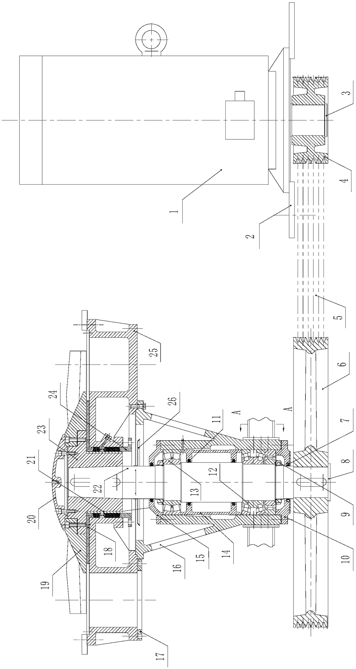
[0018] A hydraulic pulper rotor device, including: drive motor 1, motor mounting base 2, first pressure plate 3, driving pulley 4, belt 5, driven pulley 6, lip seal ring 7, second pressure plate 8 , lock nut 9, lower transparent cover 10, sealing felt ring 11, lower bearing group 12, upper bearing group 13, spacer sleeve 14, upper transparent cover 15, bearing seat 16, flange 17, flange plate 18, slurry Disk 19, sealing cover 20, sleeve 21, rotor 22, connecting shaft 23, mounting base 24, machine base 25 and blade 26, described driving motor 1 is fixedly installed on the motor mounting base 2, and described driving pulley 4 is installed on the output shaft of the driving motor 1, the first pressing plate 3 is fixedly installed on the bottom surface of the output shaft of the driving motor 1 and the first pressing plate 3 is pressed on the driving pulle...


PUM


Abstract

The invention discloses a rotor device of a hydrapulper. Main contents include that a driving pulley is arranged on an output shaft of a driving motor, a driven pulley is arranged on a rotor through key joint, and a belt is arranged on the driving pulley and the driven pulley. The lower end of the rotor is arranged in a bearing pedestal through a lower bearing group, and the upper end of the rotoris arranged in the bearing pedestal through an upper bearing group. A lower transparent cover is arranged on a bottom surface of the bearing pedestal, and the lower transparent cover is abutted against the lower bearing group. The top end of the bearing pedestal is positioned in a mounting hole on the bottom surface of a machine base. Blades are arranged on the rotor. A connecting shaft is arranged on the top end of the rotor. A slurry receiving plate is arranged on the connecting shaft. A sleeve is arranged on the connecting shaft. The sleeve is arranged in a mounting hole on the machine base through a mounting base. The rotor device is advantaged by good crushing ability, short repulping time, and convenient operation maintenance, and the device just has a dissociation function on a sizing agent and does not has a cut-off effect. The device improves repulping effect of the rotor, and reduces power consumption of equipment.

Description

technical field [0001] The invention belongs to the technical field of a pulper, in particular to a hydraulic pulper rotor device. Background technique [0002] The hydraulic pulper is a kind of equipment for crushing pulp board, waste paper and broken paper in the process of pulping and papermaking. With the increase of paper varieties and production capacity, as well as the development of waste paper treatment technology, the improvement and improvement of hydraulic pulper has become inevitable. There are many forms of pulpers, and their structures are roughly the same. They are mainly composed of tanks, rotors, sieve plates, and transmission parts, among which the rotor is the most critical. [0003] The existing hydraulic pulper rotor device is the main part of the hydraulic pulper, the size of the rotor diameter, the number, length, width, shape and arrangement position of the blades are all important factors affecting the efficiency of the hydraulic pulper. When the ...

Claims


Application Information

Patent Timeline
IPC IPC(8): D21B1/34
CPCD21B1/345
Inventor 唐浩
Owner JIANGSU DATANG MACHINERY
Why Eureka
Try Eureka