
Small household wind power generation device

A wind power generation device, a small technology, applied in the direction of electromechanical devices, wind energy power generation, wind turbines, etc., can solve the problems of blade length adjustment, high geographical requirements, large vibration, etc., to increase the shock absorption device, increase the wind area , to prevent the effect of turning too fast

Inactive Publication Date: 2018-11-30
芜湖盘云石磨新能源科技有限公司
View PDF7 Cites 2 Cited by
  • Summary
  • Abstract
  • Description
  • Claims
  • Application Information

AI Technical Summary

Problems solved by technology

[0002] In recent years, due to the increased awareness of environmental protection and the exploration of new energy sources, wind energy has attracted people's attention. As a renewable resource, wind power can provide essential electrical energy in life. However, at present, wind power generators are used Most of the installed devices are large-scale wind turbines, which have complex structures and high geographical requirements. The use of wind energy lacks mobility and flexibility, and some equipment in the home requires less power, and most of the current residences are high-rise residential buildings. , has wind resources, therefore, it is very necessary to make wind power generation equipment simpler, more convenient to operate, and go deeper into ordinary families and people. However, the existing wind power generators for households do not have shock absorbing devices. The vibration when the generator rotates is relatively large, which is inconvenient to use, and the length of the blades cannot be adjusted reasonably according to the wind force, which affects the effect of wind power generation

Method used


Image

  • Small household wind power generation device
  • Small household wind power generation device
  • Small household wind power generation device

Examples


Embodiment Construction

[0020] The following will clearly and completely describe the technical solutions in the embodiments of the present invention with reference to the accompanying drawings in the embodiments of the present invention. Obviously, the described embodiments are only some, not all, embodiments of the present invention.

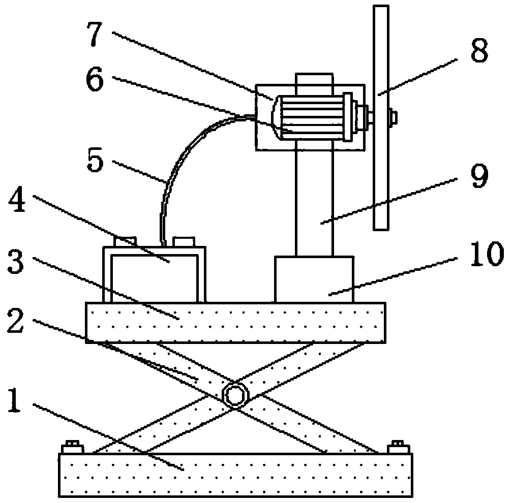
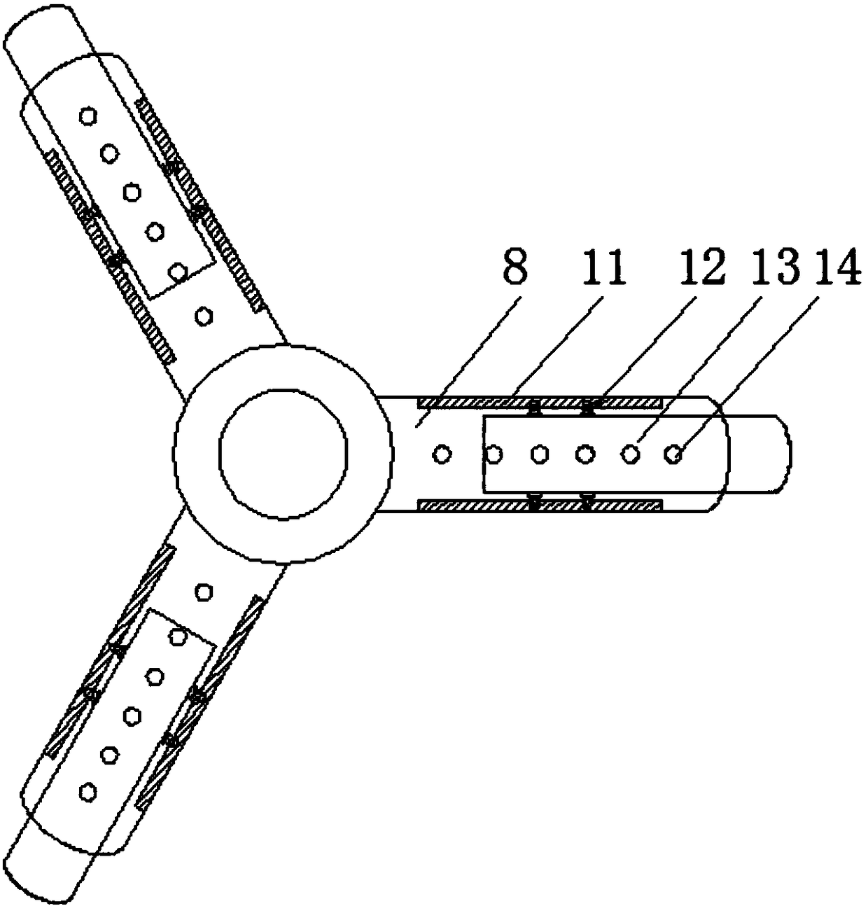
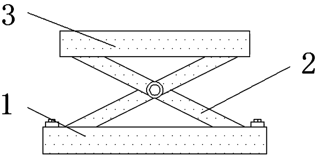
[0021] refer to Figure 1-5 , a small household wind power generation device, comprising a base 1, the base 1 is symmetrically provided with a groove 17, the inside of the groove 17 is fixedly connected with a connecting rod 15, the outer surface of the connecting rod 15 is rotatably connected with a support rod 2, the base The upper surface of 1 is fixedly connected with a spring tube 16, and the inside of the spring tube 16 is fixedly connected with a spring 18. The spring 18 and the support rod 2 play a buffer role. The upper end of the support rod 2 is fixedly connected with a top seat 3, and the top seat 3 The upper surface is fixedly connected with a battery pa...


PUM


Abstract

The invention discloses a small household wind power generation device. The device includes a base, grooves are symmetrically formed in the base, connecting rods are fixedly connected into the grooves, a supporting rod is rotatably connected to the outer surface of each connecting rod, spring pipes are fixedly connected to the upper surface of the base, and a spring is fixedly connected in each spring pipe; a top seat is fixedly connected to the upper ends of the supporting rods, a storage battery pack and a fixing block are fixedly connected to the upper surface of the top seat, the fixing block is arranged on one side of the storage battery pack, a vertical rod is fixedly connected to the upper end of the fixing block, and a sound insulating cover is fixedly connected to the outer wall of one side of the vertical rod; a power generator is transversely arranged in the sound insulating cover, fan blades are arranged at an output end of the power generator, and a wire is electrically connected to the side, away from the fan blades, of the outer side wall of the power generator. By adding a damping apparatus, the device is more convenient to use, and the wind area can be adjusted bythe device according to the magnitude of wind power.

Description

technical field [0001] The invention relates to the technical field of wind power generators, in particular to a small household wind power generator. Background technique [0002] In recent years, due to the increased awareness of environmental protection and the exploration of new energy sources, wind energy has attracted people's attention. As a renewable resource, wind power can provide essential electrical energy in life. However, at present, wind power generators are used Most of the installed devices are large-scale wind turbines, which have complex structures and high geographical requirements. The use of wind energy lacks mobility and flexibility, and some equipment in the home requires less power, and most of the current residences are high-rise residential buildings. , has wind resources, therefore, it is very necessary to make wind power generation equipment simpler, more convenient to operate, and go deeper into ordinary families and people. However, the existin...

Claims


Application Information

Patent Timeline
Patent Type & Authority Applications(China)
IPC IPC(8): F03D9/11F03D1/06F03D13/20F16F15/02F16F15/04H02K5/24
CPCF03D1/0675F16F15/02F16F15/04F03D9/11F03D13/20H02K5/24Y02B10/30Y02E10/72Y02E10/728Y02E70/30
Inventor 李让剑
Owner 芜湖盘云石磨新能源科技有限公司
Learn More